In the first part of this series [“Optimizing Induction Air,” October 2018], we explored how an engine’s intake system can be tuned to increase performance and economy. We looked at different types of inlets, examined the sizing of these inlets, and learned how to optimize ducting and the airbox for maximum efficiency.
We also covered how wave propagation in the induction runners is important to a tuned induction, and how Helmholtz resonance can increase engine volumetric efficiency by timing the frequency of the pressure waves traveling back and forth in the plenum to the induction runners. We tested this theory by attaching pressure transducers to my IO-360’s intake runner and used an oscilloscope for in-flight monitoring.
In this article, we’ll take the next step toward greater efficiency by making a tunable induction system. But first, let’s quickly review Helmholtz resonance.
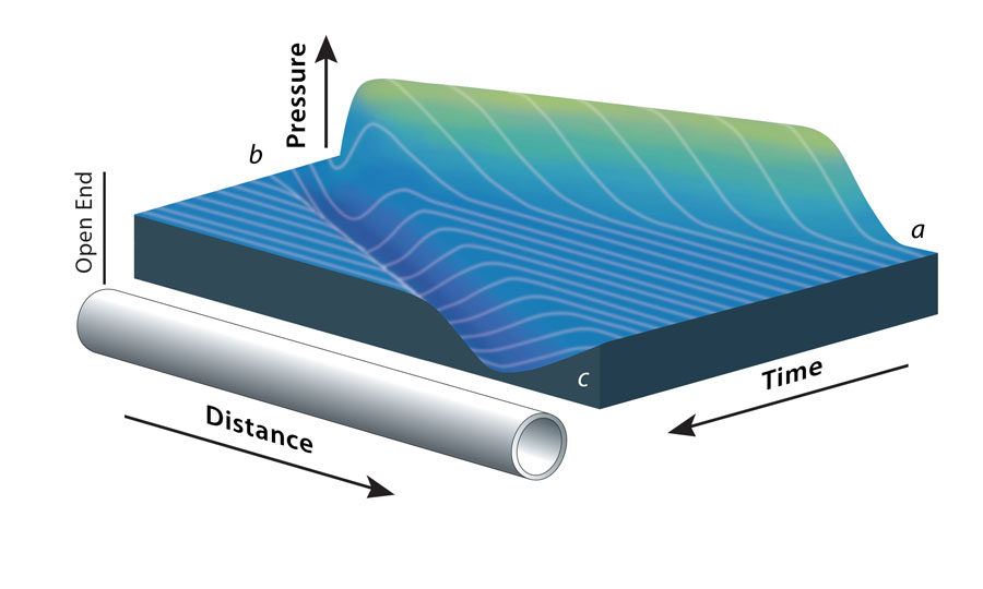
Figure 1: When the intake valve opens and the piston starts down, a pressure wave is developed at the speed of sound going away from the valve toward the plenum. For details, see “A Graphic Description of the Interaction of Waves with Various Boundaries” by D.E. Winterbone and J.R. Nichols.1
Helmholtz Resonance
I first learned about this when talking to Dr. Paulo Iscold, the aero engineer who created Anequim, the single-engine race plane that shattered numerous world speed records a few years ago. I visited him at Craig Catto Propellers in Jackson, California. What an amazing place that is. I wanted to learn what it would take to harness Helmholtz resonance in our planes.
In thermodynamics, Helmholtz free energy is a thermodynamic potential that measures the useful work obtainable from a closed thermodynamic system at a constant temperature. Well, if you understood that, all I can say is, “Wow,” and more power to you.
What is true and beneficial is to know there is something to be gained if we can harness it. In some high-performance engines, there can be as much as 7 psi or more increase at the intake valve, in part due to the proper timing of pressure waves.
Figure 1 shows what is happening when the intake valve opens and the piston starts down, creating a wave that we want back at the right time before the valve closes. When the intake valve opens, a pressure wave is developed at the speed of sound, going away from the valve toward the plenum. When the pressure wave arrives at the plenum, the great volume increase from the runner to the plenum causes the wave to reverse and return toward the valve, still at the speed of sound, and back and forth. So, if we want the pressure wave back at a specific time, we can change the distance (the runner length) and get the maximum pressure back at exactly the right time for optimum cylinder filling. This is what we have to accomplish to make a tuned induction system.
What we haven’t included is the resonance of the intake airbox (the in-line Helmholtz resonator) and plenum we introduced in the October 2018 article. This may be able to be coupled with the resonance of the runners, similar to what you see in Figure 2.
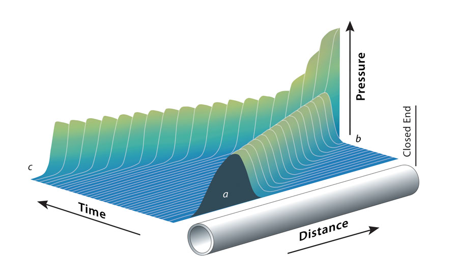
Figure 2: Helmholtz resonance added to a tuned induction system at “b.” If we can time the wave in the plenum and the in-line resonator to be at the reversal point of the pressure wave in the runner when it reverses direction at the plenum, we should be able to get the summary pressure wave at “b” in the runner.
Figure 2 shows Helmholtz resonance added to a tuned induction system at “b.” If the propagation wave from “a” to “b” is occurring in the intake runner, and the wave from “c” to “b” is occurring in the plenum and airbox, you can get a summary pressure wave increase at “b.” If we can time the wave in the plenum and the in-line resonator to be at the reversal point of the pressure wave in the runner when it reverses direction at the plenum, we should be able to increase the pressure in the runner, producing the summary pressure wave at “b,” which does not come from an indicated MAP increase from q (free stream dynamic pressure).
We have also seen this type of energy released in nature in an open-ocean wave break. This occurs frequently off the Nā Pali coastline of Kauai when the large winter swells come in. A wave runs up on a cliff, then returns out to sea as another wave is coming in, and an open-ocean wave break occurs when they collide. You see the energy released going straight up as a wave into the air. That’s the kind of energy we may be able to use with a proper inline Helmholtz resonator.
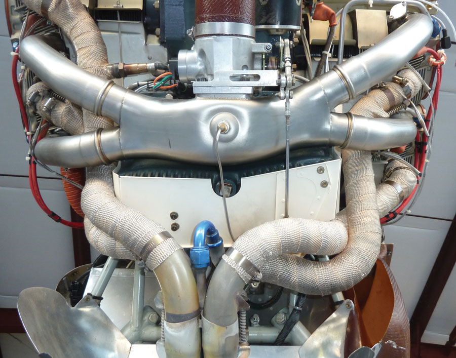
This is the latest version of the Sky Dynamics sump. I’ve used their cold induction system on my engine since the first time the plane flew about 26 years ago.
Tunable Induction
We need a tuned and tunable runner from our plenum, so I am trying to develop one, working with the cooperation of Sky Dynamics. Kevin and Marshall Murray have been very helpful and provided the components that they already make. I’ve been running their cold induction system, developed for the Lycoming 360, for 26 years or so, since the first time my plane flew.
When I originally visited with Marshall about the idea of tuned runners and wave propagation, he said that only one other pilot/builder had ever discussed it with him. That was Klaus Savier of Light Speed Engineering, although there may be others trying to develop and use intake wave propagation. I called Klaus and bounced my ideas off him.
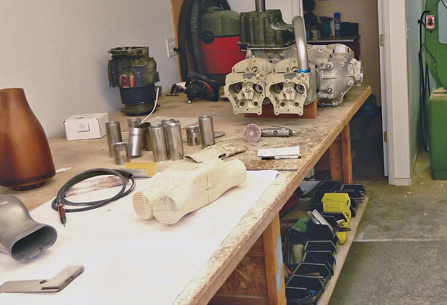
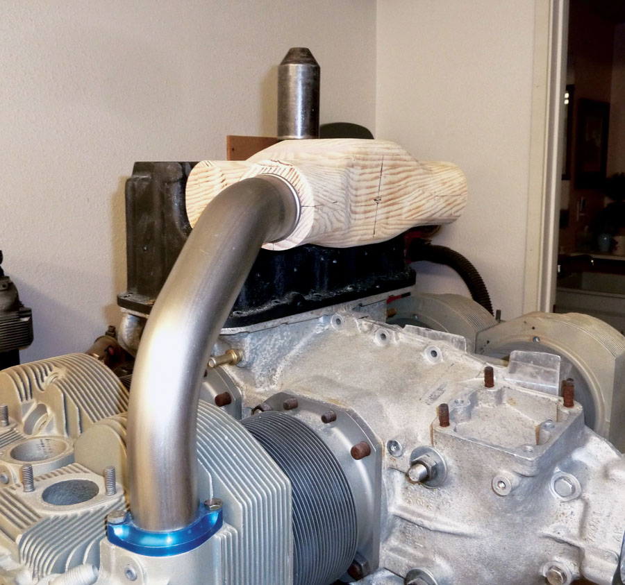
On the workbench in my shop is the mock-up engine from Kenny Tunnel at Ly-Con, along with several other parts for the project.
When I first started looking at the requirements for a tuned induction, I measured my current runner lengths and found they varied about 1.4 inches in length, with every runner being different due to the port location on the heads. The heads on opposite sides of the engine are reversed, which also contributes to the dissymmetry of the runner lengths. So, I drafted equal runner lengths from the actual head port locations, along with their respective required angles of entry into the new plenum design with the current oil sump position. I then laminated the wood plug for the plenum mold, got the components I needed from Marshall at Sky Dynamics and a mock-up engine from Kenny Tunnel at Ly-Con, and made the actual plenum mold. What a mess. Finally, I checked the fit of the plenum mold on the mock-up engine.
Test fitting a new intake runner and the laminated wood plug that was used for the plenum mold on the mock-up engine.
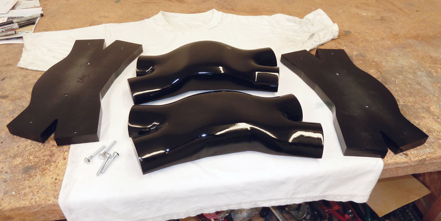
The finished mold is cut in half through the velocity stack locations on each end of the plenum. Straight flanges, added below the midline of each plenum half, allow for an easier carbon fiber layup.
The plenum volume is a little more than twice a cylinder volume, which may add to the stability of the MAP in the plenum during the intake stroke (and maybe slightly more torque). It also moved the front face of the plenum 1.0625 inch farther forward, but the throttle body is 2.5 inches shorter than my old Bendex servo, and it clears the tight areas of my Sky Dynamics 4-into-1 exhaust even better.
The finished mold is cut in half through the velocity stack locations on each end of the plenum. Straight flanges, added below the midline of each plenum half, allow for an easier carbon fiber layup.
This is where I turned to the incredible expertise of my very good pilot friends that I have met over the years. This is perhaps one of the most underestimated benefits of building an aircraft, flying it, and meeting kindred pilots. You will meet amazing people whose tremendous talents are completely different than what you have, and they will become your lifelong friends. They will be willing to help with information, techniques, and even procedures that you can’t do yourself.
I have known John Lynch of JL Design in Santa Paula, California, for about 30 years. He’s a good friend and an incredibly talented designer/engineer. I ran my ideas and the problem of an adjustable runner length that can seal to the plenum and adapt to the existing runners by him, and he produced a velocity stack assembly and manufactured the components.
After listening to my ideas for an adjustable runner length, John Lynch created this design. He then manufactured the actual parts (right). Without these components, the runners cannot be adjusted to an rpm performance target.
John’s parts are amazing! They make it possible to fine-tune the inlet runners by providing 0.750 to 0.840 inch of adjustability over 1.5+ inches of the round-trip distance the wave travels. Without these parts, the runners cannot be adjusted to an rpm performance target.
The outer aluminum component will be bonded into the plenum. John silver soldered the inner ring to the velocity stacks provided by Sky Dynamics (all four are equal-length tubes now), and the new assembly simply inserts into the existing runners already manufactured by Sky Dynamics and seals with the same O-rings they provide with their induction system.
Fabricating the Plenum
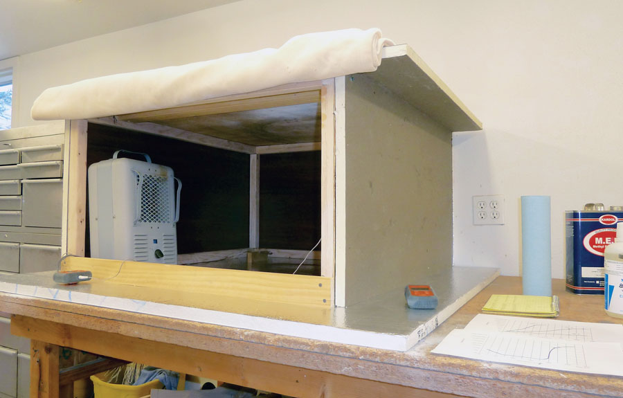
The next step was to fabricate the carbon fiber plenum and bond the assemblies into the plenum. Once again, I called my good friend Klaus Savier, who has expertise with composite structures, to discuss the type of carbon fiber and the high-temp resin necessary to live in the environment the plenum is subjected to. I ran temperature sensors to the area of the plenum and adjustable runner components, and in my case it indicated that the ambient temperature would exceed 220 F during operation in the worst-case condition, so a high temp resin was required. The resin Klaus suggested is rated to 350 F and requires a high-temp cure. Klaus showed me how to do that years ago by building an insulated tent over the part to be cured and putting a simple electric heater inside, which kind of turbocharges its output. With a simple temperature probe, you can monitor the temp inside the “Klaus homemade curing oven.” This kind of thing may be obvious to composite builders, but there may be metal guys out there that haven’t had the need for this technique.
The particular resin Klaus suggested is EPON 826, with curing agent W, from Hexion Epoxy Systems. The ratio is 100 parts of 826 to 26.4 parts W. It has an extremely long pot life (working life greater then 20 hours) and has to go through a heated curing cycle to set up. This particular resin actually gets more fluid as you start heating it, so heating ramp-up is critical to not have the resin simply run out of the carbon fiber cloth before it starts to become thicker. However, when cured it can withstand up to 350 F. If we have ambient temps higher than that in and around the induction system, then we have other more serious problems. One consideration, however, is that this part needs to be very strong in order to withstand a backfire (that’s what Klaus said).
This homemade curing oven is made from scrap wood and a 4×8-foot sheet of 1-inch Polyiso insulating sheathing. The heat source is a 1500-watt all-metal electric utility space heater.
Homemade Curing Oven
Here’s how simple and inexpensive a homemade curing oven can be: Mine is made from scrap wood to establish the shape, then I used 1-inch Polyiso insulating sheathing. A 4×8-foot sheet is about $20 from any building supply store. Its service temperature is -100 to +250 F, it’s coated both sides, and it is easy to cut square sides and edges with a Sheetrock knife. The pieces can be stacked, the edges seal together pretty good, and you can hold them in place with air-conditioning foil tape, or use a screw to hold them in place. The door is just an insulated blanket so you can get in and check everything easily. My oven is made to hold an entire Lycoming 360 so the plenum can have its adjustable runners cured in place for accuracy.
The heat source is just a 1500-watt all-metal electric utility space heater that cost about $16. I have taken out the thermal fuse and adjusted the thermostat so it will cycle on and off at above 250 F. Note that this makes it totally unsafe as a heater for any other purpose.
You’ll need to run some tests to see where the rheostat needs to be set. I used a cheap electronic temperature sensor with two probes and put one at the top in the center and one about 3 inches off the floor. This will tell you where and how hot it is in your oven. After heat soaking the oven for several cycles of the heater going on and off, everything will stabilize. This oven will hold 100 F temp to +/-4 with a 10-minute cycle. At a higher rheostat setting, it will easily reach the 250 F final cure temperature for the resin I’m using on the plenum, with it cycling at 243 +/-8 about every 2 minutes. You can just throw blankets over it to insulate it a bit more and increase the time between cycles.
Always check the curing regimen for the specific resin you’re using and its flash point. Follow those instructions to the letter. I have no idea what maximum temps this home oven is safe for, so use at your own risk.
Another point to consider: These procedures are for the average home shop and builder. They certainly can’t be compared to, or even brought up in the same thought as, the very fine work that Eric Stewart or Klaus Savier does.
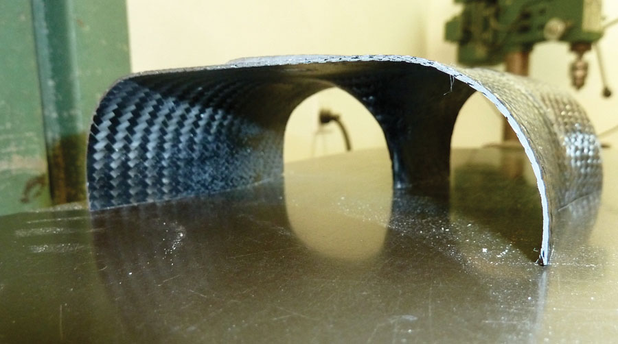
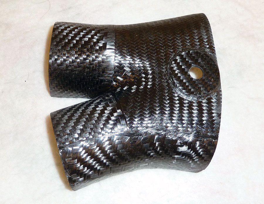
This part was used to evaluate mold survivability at curing temperatures and to determine the layup schedule.
Test Parts
To get comfortable with the Hexion resin system, I waxed my mock-up mold, applied PVA mold release, and made two test parts. One was used to check aluminum bonding, and the other was used to evaluate mold survivability at the curing temperatures and to determine the layup schedule. (The mock-up mold was made with the same technique as the actual plenum mold). Next, I surfaced the test part so it had a totally flat edge and re-cured it to check part stability for future curing cycles. I laid it on its flat edges and it was re-cured to 250 F for 3 hours; there was no movement I could detect, probably less then .002 inch.
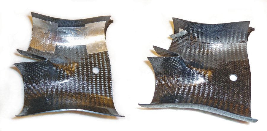
This part was cut in two and both pieces were repositioned with aluminum air-conditioning tape. The seam in the part was then covered with a multilayer carbon layup and re-cured. After curing, the aluminum tape peeled off easily and didn’t even leave adhesive residue behind.
The part was cut in two and both pieces were repositioned with the thicker style aluminum air-conditioning tape. The seam in the part was then covered with a multilayer carbon layup and re-cured. After curing, the aluminum tape peeled off with no problem and didn’t even leave adhesive residue behind. I also used this cure cycle to experiment with straight resin and Cab-O-Sil in the resin to seal porosities. Both worked well.
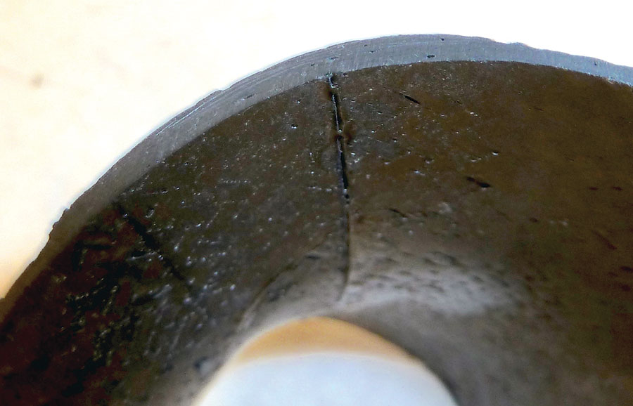
After careful inspection, the tape joint and seam seal were deemed acceptable. The small amount of porosity shouldn’t be a problem.
In the next installment, I’ll show you the process for fabricating the actual plenum. Then we’ll cover testing it on the plane.
Good Sources
- Winterbone, D.E. & Nichols, J.R., 1985. A Graphic Description of the Interaction of Waves with Various Boundaries, International Journal of Mechanical Sciences.
- Ohata, A. & Ishida, Y., 1982. Dynamic Inlet Pressure and Volumetric Efficiency of Four Cycle Four Cylinder Engine, SAE Paper 820407.
- Khoo Aik Soon, 2014. Simulation and Experimental Studies of Intake and Exhaust Tuning for Automotive Engine Low-End Torque, Universiti Sains Malaysia.
Again, I’d like to express a special thanks to all of my friends and contributors that have been instrumental in this study. Without their help, this would not be possible.


