Last month we started our discussion of wing planforms with a look at the various planform shapes in use. We now turn our attention to the effects of differing planforms on span loading and drag.
When choosing a planform, the designer must consider many factors. The goal is to come up with a wing design that provides acceptable aerodynamic performance, has good flying qualities, meets weight, strength and cost requirements, and can be fabricated with available technology. Another important consideration is drag.
The primary drag component affected by planform is induced drag, otherwise known as drag due to lift. We discussed the effect of span on induced drag in some detail in the July 2020 issue. For this month, just remember that induced drag is inversely proportional to wingspan squared. This means that a planform concept that allows greater span will probably reduce induced drag.
It’s only “probably” because of the effect of the shape on span loading. Induced drag is a function of both wingspan and the spanwise distribution of lift along the wing.
Span loading determines the second factor affecting induced drag: span efficiency. Span efficiency is a measure of how much induced drag a configuration produces relative to the induced drag of an ideal configuration of the same span generating the same lift. It is denoted by a number called the Oswald efficiency factor, which is represented in equations by the letter E and expresses the ratio of ideal induced drag to actual induced drag.
It is important to understand that this discussion is for wings of the same span carrying the same lift.
A “perfect” wing has an E of 1.0. As E goes down, induced drag goes up by a factor of 1/E. For example, a wing with a span efficiency of 85% would have 1/0.85 or 1.176 times the induced drag of a perfect wing.
Classical theory tells us that an ideal wing has an elliptical-shaped spanwise distribution of lift. Accordingly, E=1.0 represents a wing with an elliptical span loading.
The more the span load deviates from elliptical, the higher the induced drag. In general, a wing that is more tip-loaded than elliptical will have higher induced drag than a wing that is more root-loaded than elliptical, although it will have higher induced drag than a wing with a truly elliptical span load.
Recently a few planform concepts have demonstrated E > 1, but for the moment we will leave them for consideration another time.
There are also several interesting concepts that trade the loss of span efficiency of the proper non-elliptic span loading for structural advantage that allow span to increase, but for now we will consider the effect of planform shape on span loading and induced drag at constant span and lift to understand the purely aerodynamic effect. We will discuss the interplay between planform, span load and structural weight in a future article.
There have been a few airplane types built with wings with elliptical planforms to minimize induced drag. The most famous of these is the WW-II Spitfire fighter.
Elliptical wings are rare for several good reasons. The most important is that they are difficult and complicated to build. Not only is every rib different, but the wing skins have compound curvature. Likewise, the spar caps will be curved, and there are no straight element lines on the surface that form convenient control-surface breaks.
Although elliptical wings have high span efficiency and can be quite beautiful, the induced drag advantage of the shape is not large enough to overcome the other disadvantages of the configuration. While the wing is not the complete cause, it’s interesting to note that the Spitfire took 13,000 labor hours to build, while the contemporary Hurricane took 5200. For contrast, look at WW-II fighters designed with mass production in mind: The Messerschmitt Bf 109 took 4000 hours to build, and the North American P-51 got down to 2500 in full-rate mass production.
For producibility reasons the vast majority of wings are designed so that the skins are simple ruled surfaces. This means that the planform will be composed of straight-line segments. The wing will either be rectangular (constant chord), trapezoidal (straight-tapered) or a combination of the two (compound taper).
Let’s take a look at how these planform concepts affect span loading. Note for this discussion that we are looking at wings with no twist. Twist can be used to adjust the span loading, but first we need to understand what the planform itself is doing.
In today’s world, there are multiple computer codes that can be used to calculate wing aerodynamics. Fortunately, for those who do not have access to such things, there is a simple approximate method developed years ago that produces reasonably accurate results. This method, devised by Oskar Schrenk, holds that the span loading of a wing is the average of an elliptical loading, and it’s a loading that mimics the planform shape directly. The “Schrenk approximation” is still widely used for preliminary structural design for light aircraft. Details can be found here:
Constant Chord
First, let’s look at a constant-chord wing. Constant-chord wings are quite common because they are relatively simpler and less expensive to tool and build than other types, particularly for sheet-metal structures. There are penalties for this cost savings, however.
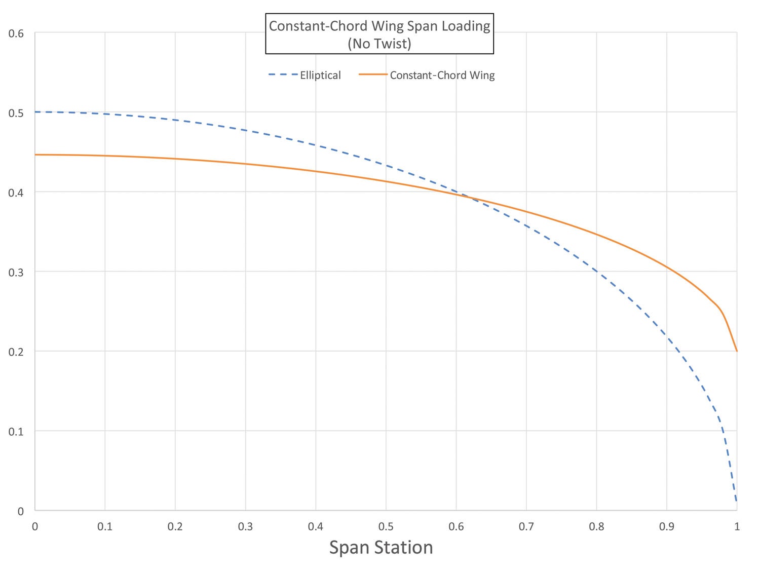
The span loading of a constant-chord wing, compared to an elliptical distribution with the same total lift, is shown in Figure 1. Note that the loading of this wing is quite far from elliptical. Moreover, the loading is shifted outboard significantly.
This has two effects: First, it will hurt span efficiency and increase induced drag. A second effect, which will be discussed in more detail in a future article, is that the centroid of the wing lift is also significantly outboard of what it would be if the loading were elliptical. This means that the bending moment is at the wing root, and the stresses in the spar will be increased accordingly.
Straight Taper
A second very common planform is the straight-tapered wing. The amount of taper is defined by the “taper ratio,” which is tip chord divided by root chord. This can be confusing since the more tapered a wing is, the lower the taper ratio. Accordingly, for example, a wing with a tip chord half as long as the root chord has a taper ratio of 0.5, while a constant-chord wing has a taper ratio of 1.0.
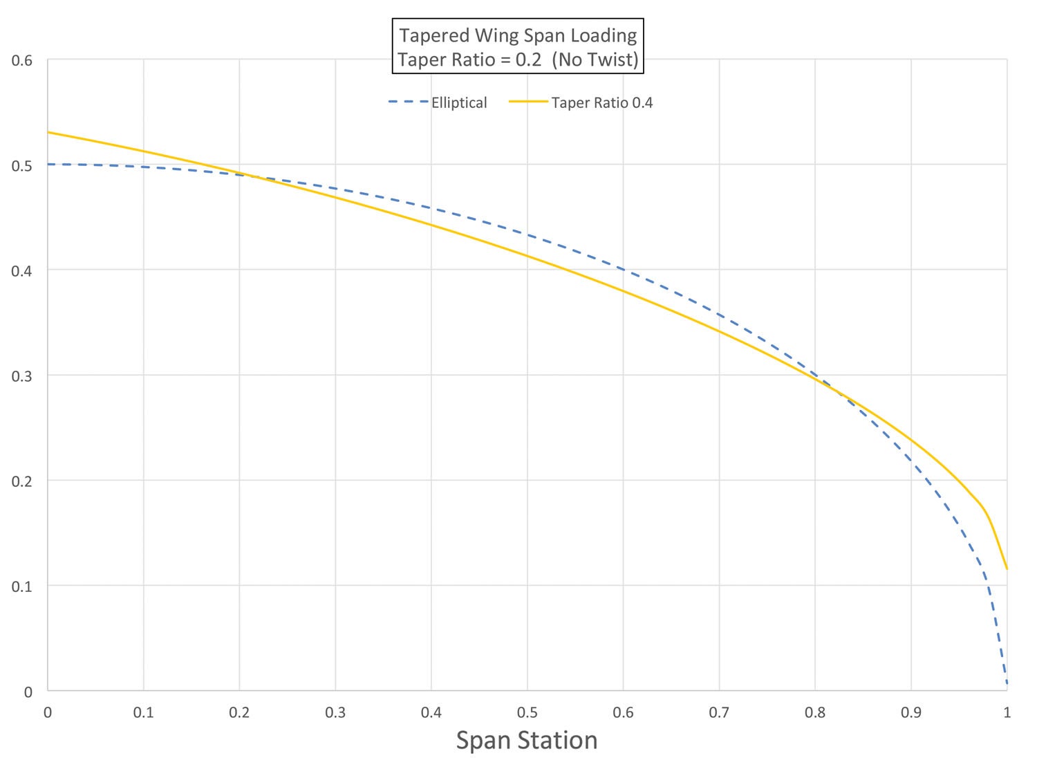
The span loading for a wing with a taper ratio of 0.4 is shown in Figure 2. Note that even though the planform is a simple trapezoid, the span loading is much closer to elliptical than that of the constant-chord wing. Accordingly, it will have a higher span efficiency and lower induced drag than the constant-chord wing shown above.
The tapered wing is more root-loaded than either the elliptical or constant-chord wing. This shifts the centroid of the lift inboard and reduces the bending moment at the wing root.
Compound Taper
There are a wide variety of compound-tapered planforms, but the most common is a wing with a constant-chord center section and tapered outer panels. This is an attractive approach for low-wing airplanes in particular since it makes the spar-fuselage carry-through in the center section straight and allows the center section to be permanently affixed to the fuselage, with attach fittings to hold on the outer panels where the spars change direction to generate the taper. If the airplane has wing-mounted landing gear, this has the added advantage of making it possible to remove the outer wings with the airplane standing on its gear.
Figure 3 shows the span load for a compound-taper wing that is constant-chord to one-half span and tapered outboard of that.
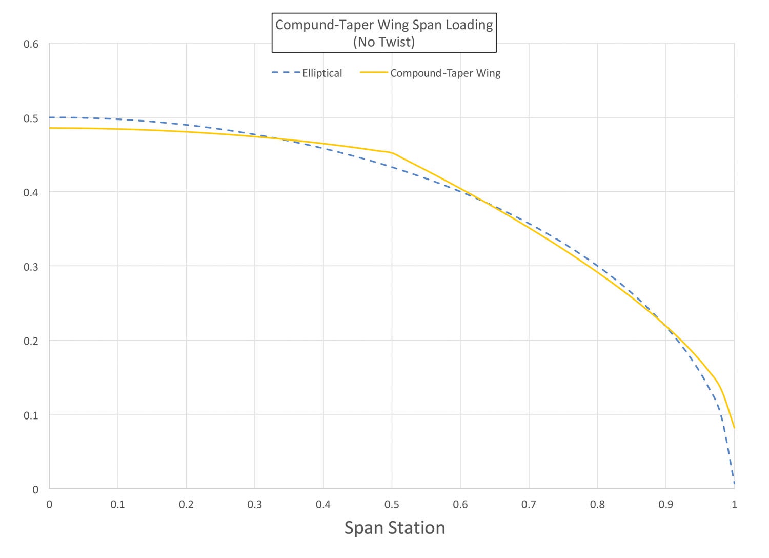
The important thing to note here is that this relatively simple planform concept generates a span loading that is very close to elliptical. It will have a high span efficiency and, as we have seen, has some configuration integration advantages.
All wing designs involve a trade-off between aerodynamics, ease of manufacture and structural weight. Next month we will continue our discussion with a look at how planform affects structure and weight.


