Last month we took a look at the effects of span and aspect ratio. At this point on the design of the wing, we have settled on wing loading, wing area and wing aspect ratio. Now that all of the fundamental sizing is complete, we can start fleshing out the other details of the wing.
The next area of interest is the shape of the wing planform. There is a lot to consider here. The planform of the wing affects its span efficiency, stall characteristics, structural layout and weight.
The designer must balance aerodynamic characteristics, structural considerations, weight and manufacturing to come to the best wing design. The relative importance of these factors varies considerably depending on the mission of the airplane.
The planform is the shape of the wing in the top view. On most airplanes, the planform of the wing is composed of a set of straight lines defining the leading and trailing edges although the shape of the extreme tips may vary. This is because a wing planform with leading and trailing edges composed of straight-line segments has a skin composed of a set of single-curvature ruled surfaces. This allows the wing skin to be made of sheet material (metal, plywood or fabric) with a single curvature that can be fabricated and applied without stretch forming or molding.
In addition to allowing ruled-surface skins, the fact that the element lines of the surface (lines of constant-percent chord) are straight means that the spars can have straight caps and that the hinge lines of control surfaces that have a constant-percent chord width are also straight.
All of this makes the fabrication of the wing and its components much easier. For the vast majority of airplanes, any performance gain to be had from deviating from a ruled-surface wing is small enough that it does not justify the additional cost and complexity that arises from building a more complex shape.
This is particularly true in the general aviation world. High-speed aircraft, like airliners and military airplanes, can benefit from more complex wing shapes, particularly if they cruise in the high subsonic speed regime (Mach 0.75 to Mach 0.95) where minimizing the development of shock waves on the wing is of paramount importance. Even here, designers tend to use planforms composed of straight lines despite the fact that the development of the twist and airfoil shapes along the span may force the use of compound-curved skins.
The advent of molded composites has given designers a lot more freedom to use compound curved shapes on aircraft, so some of these restrictions have eased in recent times. In spite of this, many of the issues that arise from compound-curved skins, curved spar caps and nonlinear hinge lines remain. With all of this in mind, let’s take a look at some of the more common types of wing planforms.
Planforms are characterized by the way the chord of the wing varies along its span. The local wing chord is defined as the distance between the leading edge and trailing edge measured along a line parallel to the centerline of the airplane in top view.
Taper Ratio
Before we discuss wing planforms in general, we need to introduce one geometric parameter that is often used to characterize the wing. The taper ratio of a wing, represented in equations by the Greek letter lambda (λ), is the ratio of the tip chord to the root chord.
λ = Ct/CR
The more tapered a wing is, the smaller the taper ratio. On a constant-chord wing, where the root and tip have the same chord, the taper ratio is 1.0. If the tip chord is half the root chord, the taper ratio is 0.5, and a wing with a pointed tip or triangular planform has a taper ratio of 0.0.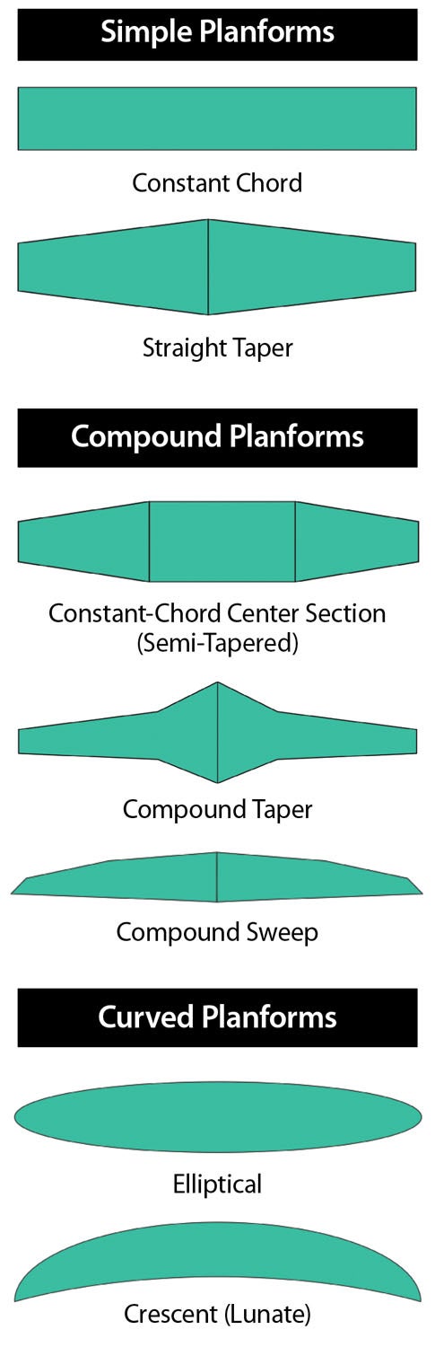
Common Planform Shapes
Constant Chord
The simplest wing planform of all is a constant-chord wing: the leading and trailing edges are parallel. Except for the tips, which might be rounded or have a variety of molded shapes, the planform of the wing is a simple rectangle.
Constant-chord wings are very common on light airplanes. While they have poorer aerodynamic performance and tend to be heavier than more complex wing shapes, they have the very significant advantage that all of the ribs are the same and the spars have a constant height. This makes them cheaper and easier to design and manufacture.
For a large number of general aviation applications, the savings in cost and reduced complexity afforded by the constant-chord wing are sufficient to overcome the weight and aerodynamic performance penalty.
Straight Taper
A second common approach to wing design is to use a simple tapered wing. On a simple tapered wing or “straight-tapered” wing, both the leading and trailing edges are formed by a single straight line. The tip chord is smaller than the root chord, giving the wing a trapezoidal planform.
Tapered wings have better aerodynamic efficiency than constant-chord wings and are also more structurally efficient. The price of this improved efficiency is greater complexity in the structure and a few aerodynamic issues (to be discussed in a future edition of “Wind Tunnel”) that make getting acceptable flying qualities a bit more of a challenge.
Sometimes this trade-off ends up favoring the tapered wing in spite of its issues. For higher-performance airplanes and for missions where efficiency is important, a tapered wing is often the preferred approach.
Compound Taper
The next class of planforms have more complex shapes, which are formed by a series of straight-line segments. There are several types of “compound-taper” planforms that are used.
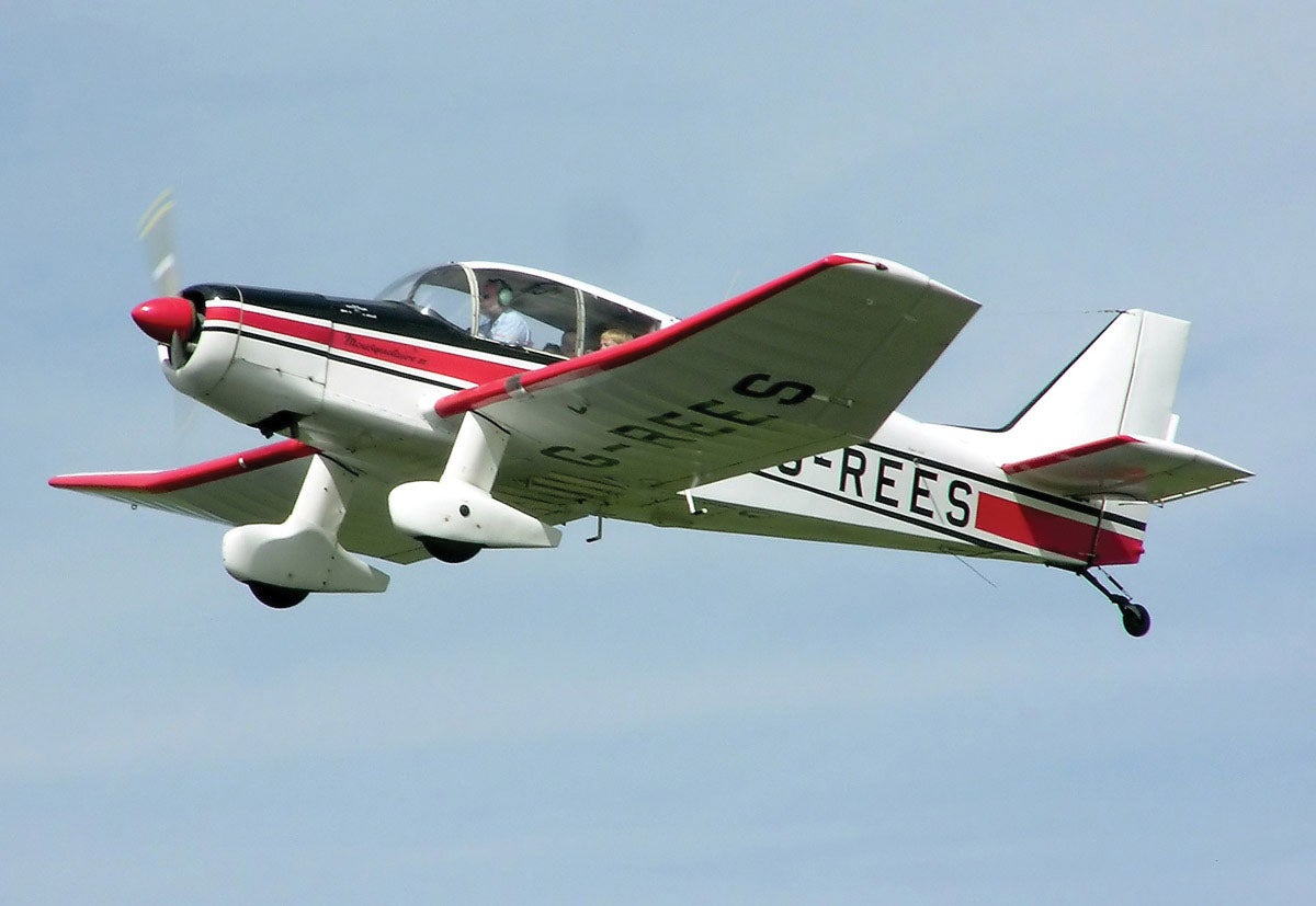
The first of these is a wing with a constant-chord center section and tapered outer wing panels. These wings are sometimes called “semi-tapered” (a terminology I personally dislike). This approach is most commonly used on low-wing airplanes. Examples of this type of wing can be found on the KR-2, Bushby Mustang 2 and the French Jodel and Robin designs.
The constant-chord center section allows the wing spars to carry straight through the fuselage and be permanently attached. Attach fittings are used to connect the tapered outer panels to the center section. The wing dihedral starts at the break between the center section and the outer panels so the wing-attach fittings do double duty as the dihedral break.
If the airplane has wing-mounted landing gear, it can also be mounted to the permanently attached center section so the airplane can remain on its landing gear when the outer wing panels are removed for maintenance or transport.
An alternate version of this approach has a much longer constant-chord wing with a relatively short, highly tapered tip section. This approach allows the wing to have significantly better aerodynamic efficiency than a pure constant-chord wing while retaining most of the structural simplicity and manufacturing advantages of the constant chord planform. Examples can be seen on the Wittman Tailwind and on Aleš Strojnik’s motorgliders.
A second common compound-tapered design is one in which the wing chord tapers relatively sharply inboard and transitions to a more gradual taper outboard. The break in the planform where the taper changes can be in the leading edge, the trailing edge or both. This concept is used when structural or configuration integration considerations make a larger root chord desirable. One example of this is when the extra taper is all in the leading edge to make room in the wing root to stow a retracted landing gear either ahead of the main spar or between a pair of more widely spaced spars.
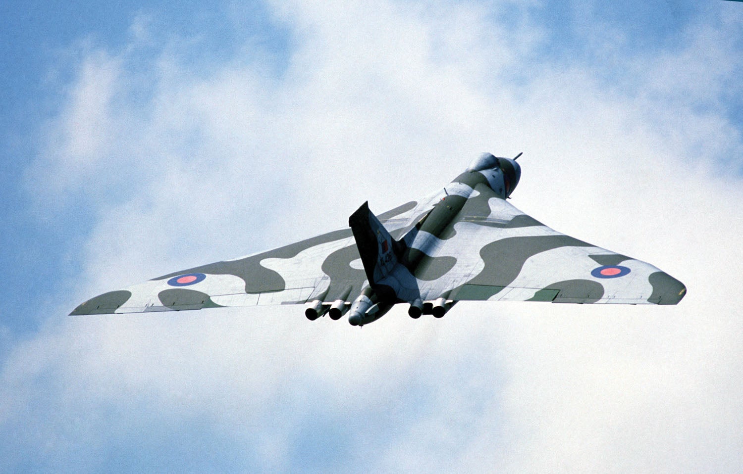
A third compound planform has a straight trailing edge and a leading edge composed of line segments that have progressively more sweep moving outboard on the planform. Some examples of this are the Schempp-Hirth Discus sailplane and the British Avro Vulcan bomber. The primary attraction of this approach is that it can provide a very aerodynamically efficient wing without resorting to a curved planform with compound-curved skins.
Curved Planforms
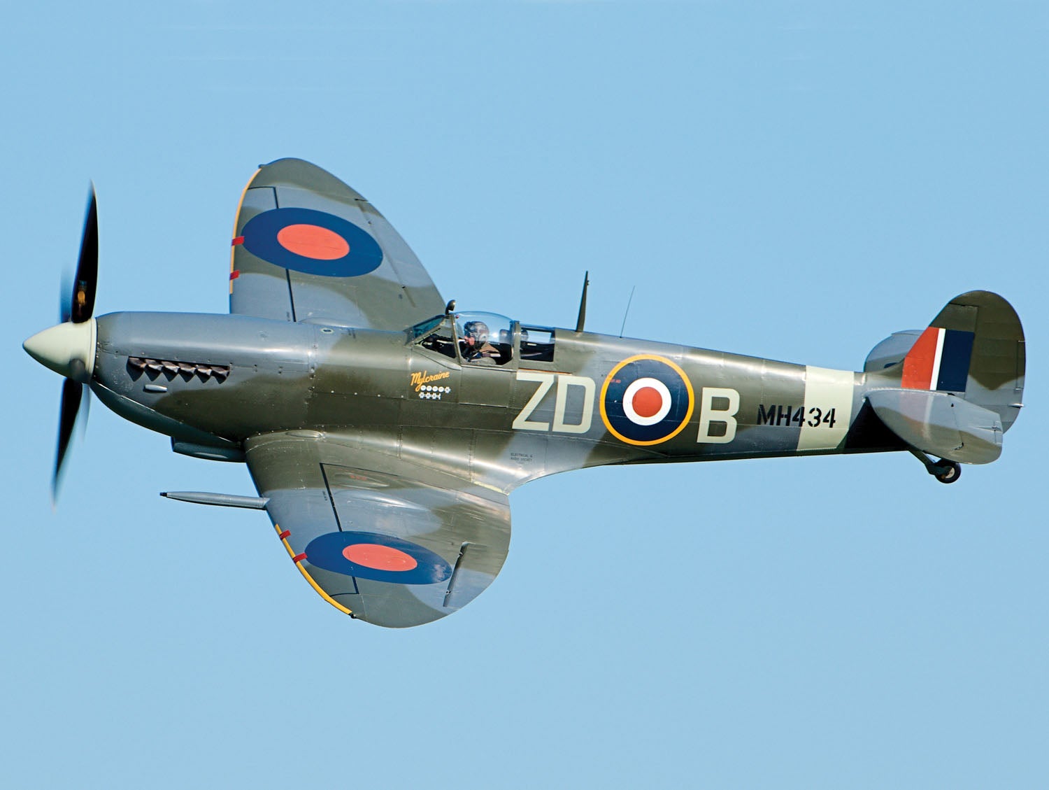
Elliptical
There are two wing planfoms with curved edges that are of significant interest. The first is an elliptical shape as seen on the Spitfire WW-II fighter. The attraction of an elliptical wing is that classical aerodynamic theory shows that a wing with an elliptical span loading will have the lowest induced drag for a given lift and span. Sometimes a designer will decide that the extra complexity involved in building an elliptical wing with compound-curved skins is an acceptable price to pay to get that last bit of aerodynamic performance.
Crescent or Lunate
Some years ago, researchers studying fast-swimming marine creatures noticed that they all shared the same crescent shape for their propelling fins and tails. This led to more detailed study of the aero/hydro dynamics of this shape. What that research uncovered is that such a shape is actually more efficient than the theoretically optimum elliptical shape.
The increase in efficiency happens because the flow over crescent-shaped wings does some highly nonlinear things that are not taken into account by the linearized lifting-line theory used to derive the “optimum” elliptical shape. The basic natural selection “eat or be eaten” effect iterated over a very long time in the wild proved to be a more effective optimizer than linearized mathematical theory.
Next month we will take a more detailed look at how the features of these various planforms affect the design and how the designer can balance these considerations to reach a final wing design.


