For the last few months, we have been looking at how the planform affects both the distribution of lift and the distribution of lift coefficient (Cl) along the span of the wing.
The most important thing to remember from this discussion is that the planform controls how the lift and lift coefficient distributions vary with angle of attack. The lift and distributions of a wing with no twist are called “additional” distributions because they scale linearly with angle of attack. At zero total lift, the additional distribution is zero everywhere along the span. As angle of attack increases from the angle of attack for zero lift, the distribution scales linearly.
The only way to affect the additional distributions of lift and Cl is to alter the planform.
This is not the only way to affect the total lift distribution, however. The designer also has the option to twist the wing to affect the angle of attack along the span.
Basic Lift Distribution
If we look at a wing with zero twist, at an angle of attack for zero lift, the lift is zero at every point along the span. This changes if we twist the wing.
For reasons we will discuss in a moment, it is common to twist the wing so that the tip is leading-edge-down (lower AOA) than the root. This is called “washout.” If the twist is in the opposite direction so the tip is leading-edge-up relative to the root it is called “wash-in.”
Because twisting the wing alters the local angle of attack of each piece of the wing, the local lift is also altered by the twist. The lift increment caused by the twist is constant and does not vary with angle of attack.
If we look at the lift distribution of a wing with washout at an angle of attack where the total wing lift is zero, we will see positive lift inboard and negative lift outboard. This lift distribution at zero total wing lift is called the “basic distribution.”
The distributions of total lift and Cl across the span at any angle of attack are the sum of the basic distribution (constant with AOA) and the additional distribution (varying linearly with AOA).
Accordingly, by properly selecting the twist distribution, the designer can tailor the lift distribution of a wing of any planform.
Twist Distribution
The first thing we need to understand is the way twist varies along the span for typical wings. In order to properly determine the aerodynamic effect of twist, we need to know the actual geometric incidence at every point along the span.
It is very common to say a wing has “linear twist.” This usually means that the leading and trailing edges are straight lines so that the skin of the wing is a single-curvature ruled surface. It does not mean that the actual twist in degrees varies linearly along the span.
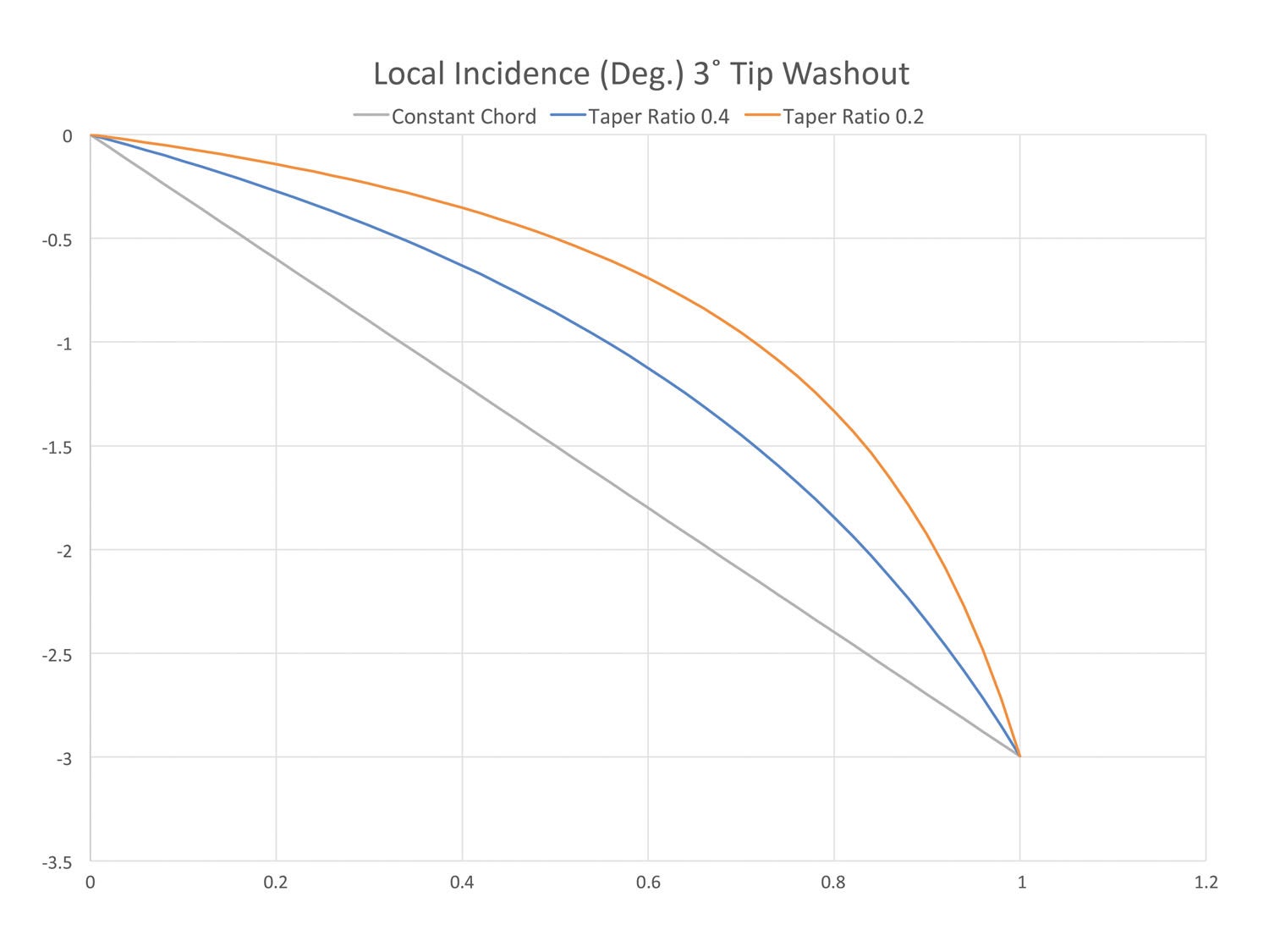
Figure 1 shows the twist distribution for three wings of different taper. All have 3° of washout at the tip and linear leading and trailing edges. Note first that the twist distribution of the constant-chord wing is indeed linear. Then look at the curves for the tapered wings. We can see that as the taper of the wing increases (smaller taper ratio), the twist distribution becomes more and more nonlinear, with most of the twist happening in the outboard portion of the span. This is neither good nor bad per se, but it’s important to get the right geometric twist distribution before starting to calculate span loads.
Aerodynamic Effects of Twist
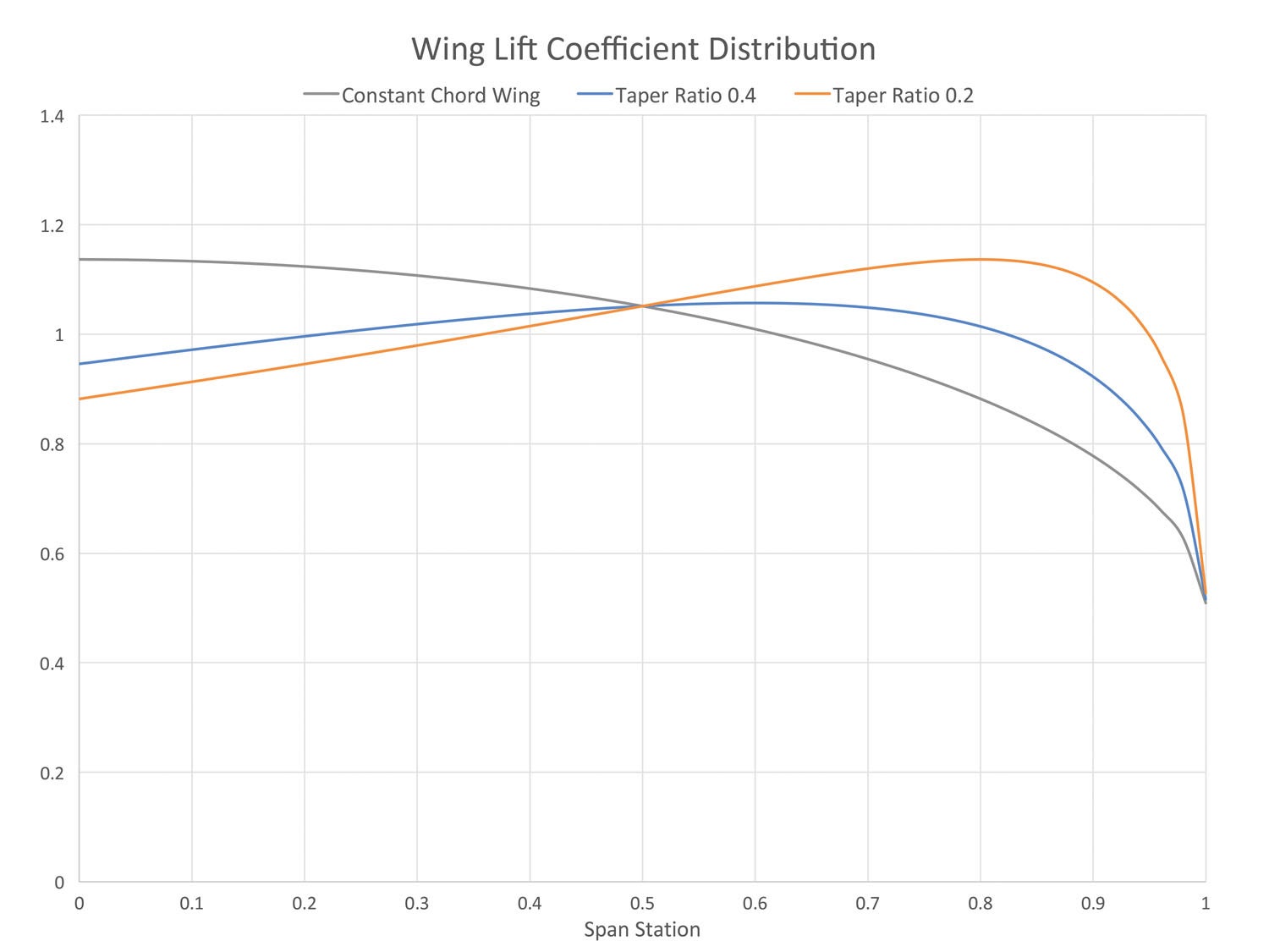
Local Lift Coefficient (Cl) Distribution: As we saw last month, as a wing becomes more tapered, the additional Cl distribution shows ever-higher values of Cl outboard. Figure 2 (repeated from last month) shows this. The tapered wings as illustrated in Figure 2 will have a tendency to stall first well outboard on the wing. This is highly undesirable and can lead to the airplane rolling off at the stall and tending to spin.
The way to alleviate this problem is to twist the wing.
Figure 3 shows the effect of twisting the taper ratio = 0.4 wing. The example wing has 3° of washout.
Three curves are shown in the figure. The first (gray) curve shows the same zero-twist Cl distribution shown in Figure 2 for this planform (additional Cl distribution).
The second (orange) curve shows the Cl increment due to the twist in the wing (basic Cl distribution). Because the wing has washout, the basic distribution shows positive lift inboard and negative lift outboard. You can also see that this distribution is not linear because of the spanwise variation of geometric twist for a wing with straight leading and trailing edges that we discussed earlier.
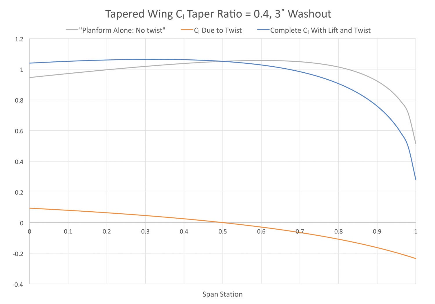
The third (blue) curve shows the total Cl distribution that arises from the summation of the basic and additional distributions at this angle of attack. The addition for the 3° washout moves the point of maximum local Cl inboard from approximately 65% of the span to about 30% of the span.
By choosing the proper amount of twist, a designer can ensure that the wing starts stalling well inboard, which will produce safer stall characteristics.
Lift Distribution: Up to this point we have been looking at the local lift coefficient (Cl). Twisting the wing also affects the spanwise distribution of lift (L).
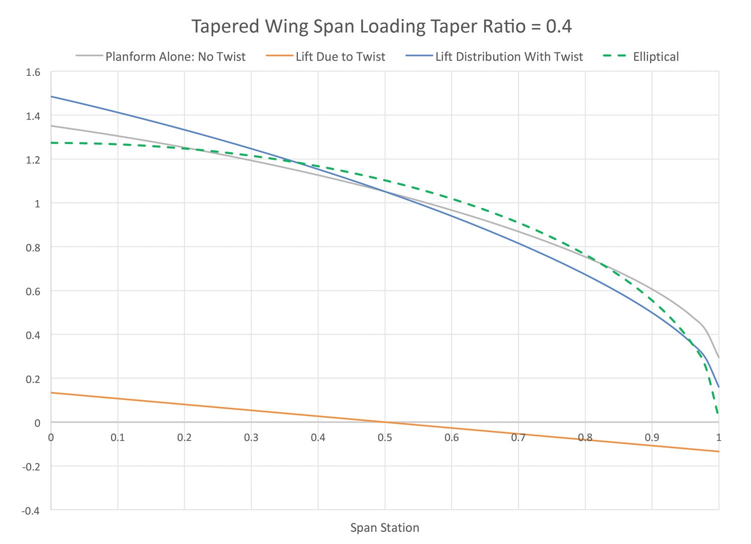
Figure 4 shows the lift distributions for the same 0.4 taper ratio wing we just looked at the Cl distributions on. Once again, we can see that the effect of adding washout to the wing is to shift the lift distribution inboard. The ideal elliptical distribution of lift is also shown (green dotted curve). This shift in span loading affects the span efficiency and induced drag of the wing. For a wing with this much taper, the span loading shifts slightly farther away from the ideal elliptical distribution so there might be a small penalty in induced drag.
This must be viewed in the context that the tapered wing has significant aerodynamic and structural advantages as we have seen over the proceeding months. The very small induced drag penalty due to twist is a worthwhile trade-off to give the airplane safe flying qualities. The inboard shift of the load also reduced wing root bending moment, which as we have seen can reduce the weight of the wing or allow a small span extension at constant weight. Overall, a properly twisted, tapered wing can be designed to have essentially no drag penalty over an untwisted wing.
For some planforms, twisting the wing properly can actually increase span efficiency and reduce induced drag. This is the case for a constant-chord wing.
Looking back at Figure 1, we can see that a constant-chord wing has its maximum local lift coefficient (Cl) at the root, so it is likely to have relatively benign stall characteristics even without twist. That said, it’s not uncommon to put a bit of washout in a constant-chord wing just to make sure the stall characteristics are benign.
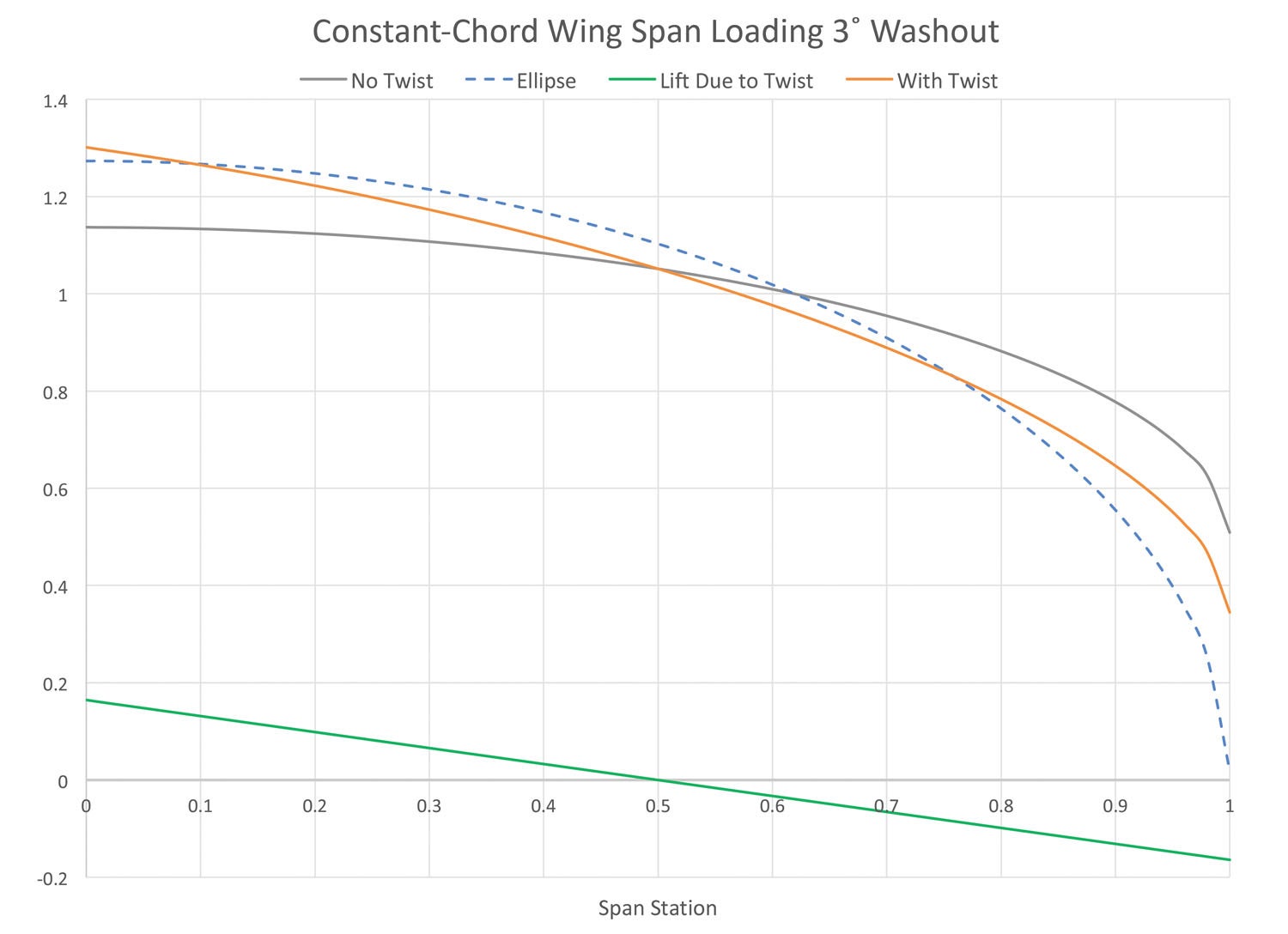
Looking at the spanwise lift distribution for the constant chord wing shown in Figure 5, we can see that adding twist to the constant chord wing actually moves the span load closer to the ideal elliptical distribution and will improve span efficiency and reduce induced drag.
For any planform it is possible to twist the wing to get exactly the span load we want at a single flight condition. Because the additional loading is a function of planform, the span load will move away from this chosen span load as flight condition changes, but if the wing is optimally twisted for the cruise point, significant range performance gains are possible.
This is well beyond the scope of what most general aviation aircraft exhibit because it may require complex, nonlinear twist distributions, but for long-range transport planes, optimizing twist is a significant part of the overall wing design process.
One Final Caution for Builders
It is sadly common for builders to decide to build their wings without the designed-in twist in an effort to reduce drag. This almost always ends up making the airplane worse. Removing washout will tend to give the airplane unpleasant—or even dangerous—stall characteristics. Removing washout shifts the span load outboard, which increases the loads on the wing root and reduces the structural limit load of the airplane. It rarely reduces drag and, as we have just seen, can sometimes increase it. The designer put the twist in the wing for good reasons. A prudent builder will respect those reasons and build the wing as designed.


