Last month we started our discussion of wing design with a look at the vertical placement of the wing on the fuselage (high versus low). We now turn our attention to the structure of the wing.
In flight, the wing generates the lift that holds the airplane’s weight up. It also generates additional lift above the weight of the airplane for maneuvering and in response to gusts.
Loads
The total load the wing structure must carry varies by category. Light airplanes certified under FAR Part 23 must be able to sustain a limit load factor of 3.8 G’s for the lightest machines, dropping to 3.0 for airplanes certified at the maximum gross weight covered by Part 23 (typically small twin-engine transports).
At the other end of the spectrum, fighters are designed to limit load factors between 7 and 9 G’s and unlimited aerobatic airplanes are typically designed to a limit load of 10 G’s.
Load Paths
At the outset of wing design, the initial decision the designer must make is the structural concept for the wing, which will define the load paths that carry the wing loads in flight.
The lift of the airplane is generated on the wing, but the majority of the weight that reacts to the lift is in the fuselage. Because of this, there is a large bending moment at the root of the wing. Accordingly, the wing must have a substantial structure with load paths that transmit the wing loads across the fuselage.
There are a large number of possible wing and airplane configurations, but for now we will primarily confine our discussion to monoplanes with wings attached directly to the fuselage and leave biplanes, triplanes, parasol designs and other more exotic configurations for another day.
Structural Concepts
There are two primary structural concepts used for wings. The most common in the modern world is the cantilever wing. The second approach is called an externally braced wing.
Cantilever
On a cantilever wing all of the structure is contained within the wing itself. One or more spanwise spars inside the wing carry the majority of the wing bending moments. The wing is attached to the fuselage at the root, and there is a carry-through structure within the fuselage that provides a continuous tip-to-tip load path for the wing’s main load-bearing spars. There are several concepts used for the carry-through structure that we will look at in a later discussion of detailed wing structural integration.
Early airplanes had very thin airfoils that could not contain spars that were deep enough to handle the loads. Beginning during WW-I, thicker airfoils were developed that had relatively low drag and were thick enough to allow designers to place strong enough spars inside them to withstand flight loads without any external struts or wires. Because of this, early cantilever wing designs were referred to as internally braced wings.
Braced
An externally braced wing also has spars, but in addition to the spars it is supported by additional structural elements that are outside of the wing itself.
These external elements are a fundamental component of the wing’s structure and carry much of the load. They attach to the wing spars well outboard of the wing root and join the fuselage or other bracing structure at points significantly above or below the wing root.
There are two types of structural elements that are used to accomplish this bracing function: wires or struts.
Wires
Early airplanes used wire-braced wings. Their wings used very thin airfoils that were essentially cambered thin plates. These were far too thin to contain spars that could carry the bending loads on the wings. Biplanes featured diagonal wires between the wings so that the combination of the wing spars, interplane struts and crossed bracing wires formed a stiff box girder that was structurally similar to truss bridges, which were relatively well understood at the time. The ability to form a box structure that was stiff both in bending and torsion was one of the primary reasons that so many early airplanes were biplanes.

Wire bracing was also used on monoplanes. On wire-braced monoplanes there were two sets of wires above and below the wing to handle both positive and negative lift loads. Wires take loads in tension but not compression, so a wire-braced structure must have wires in two directions to both lift and “droop” the loads. The lift wires are attached to the bottom of the fuselage, or sometimes to a fixed landing gear structure, while the “droop” wires run up to either the top of the fuselage or a strut above the wing called a king post. The WW-I Fokker Eindecker was an early fighter that used this configuration.
Wire bracing persisted as a feature of state-of-the-art airplanes surprisingly late. In the quest for speed, designers wanted to keep the wings thin because they believed it was the path to lower drag. Streamlined cross-section wires had been developed to reduce the drag penalty of the wires. A major reason wire bracing persisted on fast airplanes was that wire-braced wings could be made very stiff in torsion by the wires. Aileron flutter was poorly understood at the time, and the high torsional stiffness of wire-braced wings helped prevent flutter in a world where aileron mass balancing had not yet been invented.
The ultimate wire-braced monoplanes were the racing seaplanes developed to compete for the Schneider Trophy. In 1930, the British Supermarine S.6B won the trophy outright and then set an absolute world air speed record of 407.5 mph. In October 1934, the Italian Macchi M.C. 72, which had not finished development in time to compete for the Schneider Trophy, set a record of 440.7 mph. This record still stands today as the record for piston-engine seaplanes. It’s remarkable to me to consider that the S.6B and M.C. 72 were both open-cockpit airplanes with wire-braced wings.
Struts
Struts are rigid members used to brace the wings. Unlike a wire, a strut can carry load both in tension and compression, so strut-braced wings typically need either a single strut or a pair of struts (above or below) on each side of the wing. The wing spar and the strut system form a triangle in the front view. Inboard of the strut/wing junction, the upper member is loaded in compression in upright (positive G) flight and the lower member is loaded in compression. This means that on a high-wing airplane, the wing spar is in compression and the struts are in tension. On a low-wing airplane the converse is true.
Design Decision
The choice of cantilever versus braced wing is a trade-off between weight, drag and configuration integration issues. For a given wing area and span, a cantilever wing will have lower drag than a braced wing but will weigh more. For a given weight, a braced wing can have a greater span than a cantilever wing of the same area.
This means that, in general, the cantilever is superior for missions where reducing parasite drag is desirable, and the braced approach works well for missions where high speed performance is less important and the parasite drag of the bracing trades favorably against the reduction in weight and/or induced drag provided by the superior structural efficiency of the braced wing.
Accordingly, almost all airplanes designed primarily for fast cross-county flying have cantilever wings. Slower flying sport and utility airplanes often have strut-braced wings.
Interestingly, some studies of advanced airliner configurations are revisiting strut bracing. Transport wing aspect ratios are reaching the limit of what can be achieved structurally, even with composite structures. Experiments and analyses are currently underway to see if the increase in span and reduced induced drag enabled by external bracing can increase cruise efficiency enough to offset the parasite drag penalty of the strut and give an overall increase in cruise L/D.
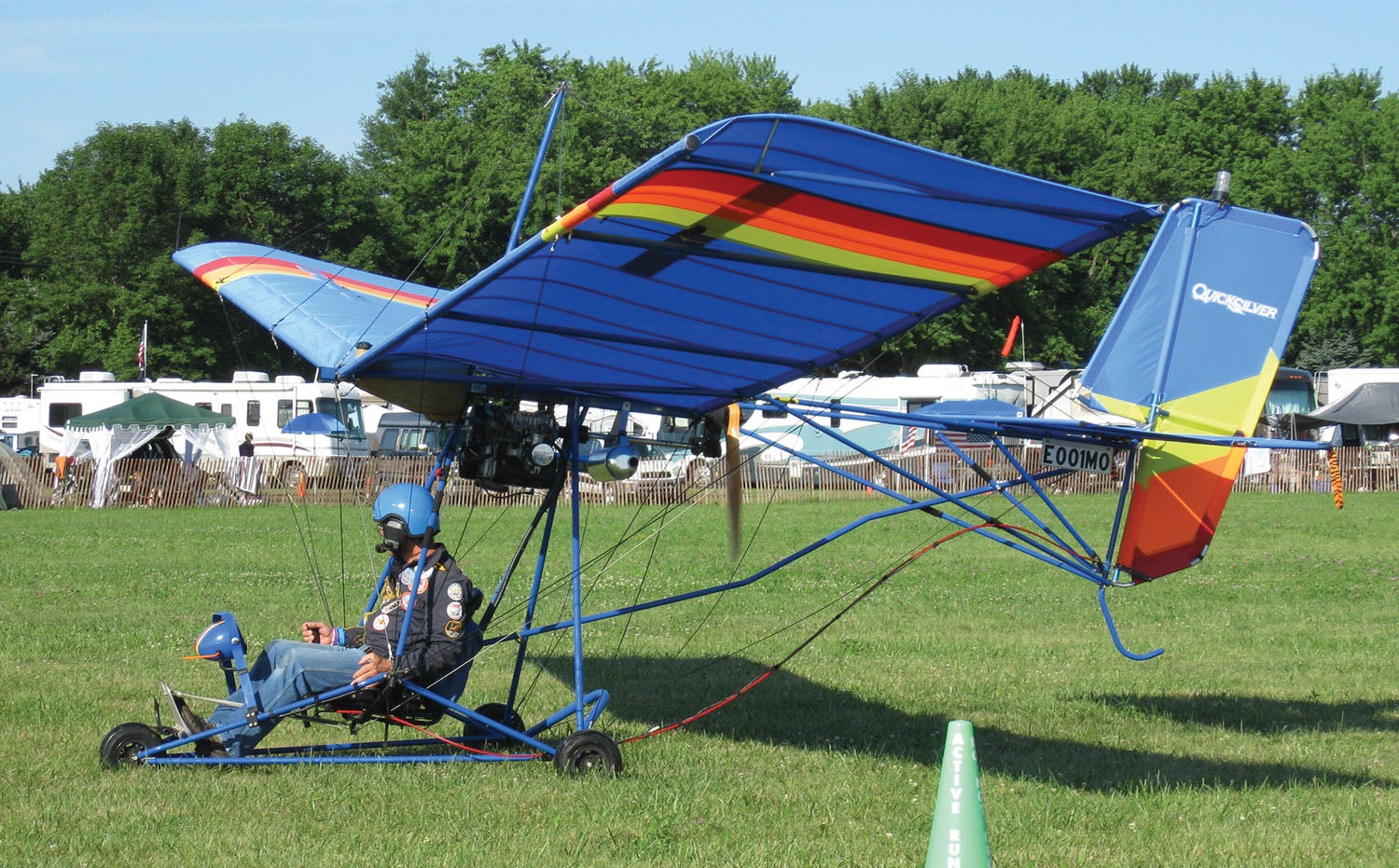
Wire bracing has essentially disappeared except for true ultralights, where the very strict FAR Part 103 empty weight limit, combined with the mandated slow stall speed, dictate a large, very light wing. In this special case, the high parasite drag of the multiple wires is acceptable in order to meet the weight and wing loading requirements imposed by the regulations.
Wire bracing is also still used on the horizontal tails of some airplanes. These machines have tails that are made of tubing covered with fabric. The flat-plate tube-structure tail is too thin to cantilever, so struts or wires are used to brace it.
Next month we will take a look at some of the details of the structural design and integration of the wing.


regarding – “Accordingly, almost all airplanes designed primarily for fast cross-county flying have cantilever wings. Slower flying sport and utility airplanes often have strut-braced wings.”, a notab;e exception is the Wittman Tailwind – it is a fast cross country cruiser with a high strut braced wing. Note the wins by Red Hamilton in his class in a Wittman W10.
Great series of articles.
Electrostatic Wing design is in its infancy stages now. The DoD HAS DECLASSIFIED the technology so it can now be used on smaller light aircraft. The only thing being required is the power source on board the aircraft to create the electrostatic propulsion which required extremely high DC voltage. This wing propulsion is silent and fast. Current wing design will have to change to accomadate this concept. We can do away with propellers technology. and gasoline motor technology that has rulled our skies since 1910. The more voltage you apply, the faster you can go, and there is no sound berrier to break. The electrostatic field wraps around the aircraft and protects it from the frictional air. In other wards it rides in a electron bubble. But back to the wing structuire, if you have worked for these great companies, you should know it is coming.
Comments are closed.