The size and shape of the planform of the vertical tail determine its ability to perform its stabilizing and control functions.
In steady-state cruise flight, the wing of the airplane is producing lift, and the horizontal tail is usually generating some lift or downforce to trim the airplane in pitch. The airplane cruises at zero sideslip angle and, as a consequence, the side force on the vertical tail is either zero or quite small. What this implies is that the cruise drag of the vertical tail is primarily parasite drag. The wetted area and airfoil of the tail affect parasite drag, but the planform has little effect. This gives the designer a bit more freedom to choose the planform of the tail.
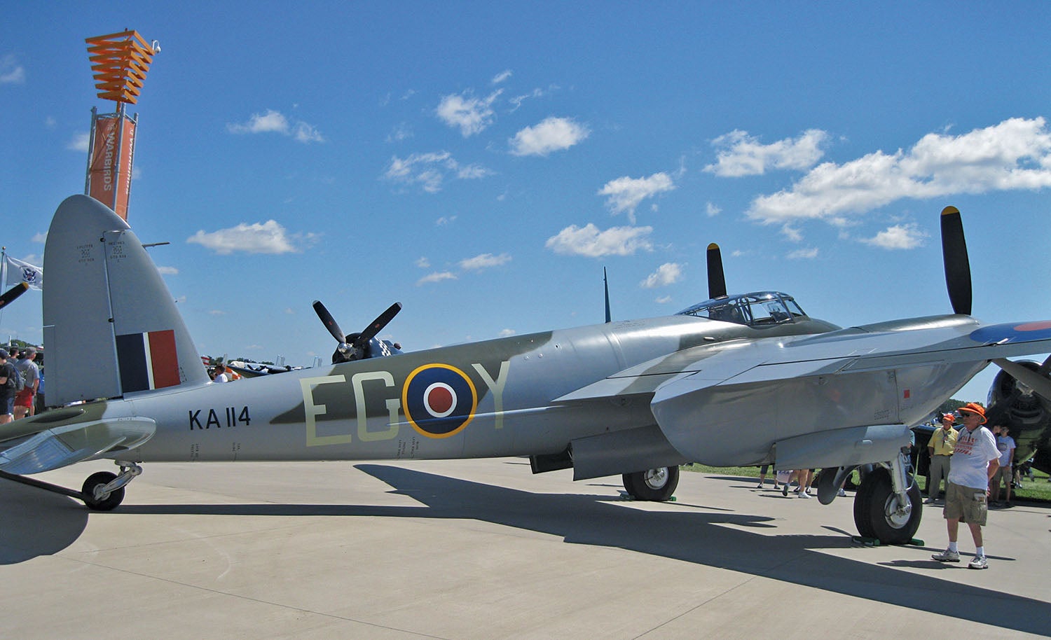
One result of this has been that some designers adopt a “trademark” vertical tail shape as a distinctive visual signature. Two good examples of this are the elliptical tail planform on De Havilland airplanes, all the way from the Moth biplanes to the Vampire jet, and the Mooney swept-forward tail in the general aviation world.
Sweeping the vertical tail back does have some aerodynamic effects, as we shall see in a moment, but it is often more a styling statement than an engineering decision.
Vertical Tail Volume Coefficient for Sizing the Fin
In preliminary design, you can get an initial estimate of the required vertical tail area by correlation with existing aircraft using the vertical tail volume coefficient (Vv). The vertical tail volume coefficient is similar to the horizontal tail volume coefficient we saw during our discussion of horizontal tail sizing. The difference is that Vv is normalized using wingspan as the reference length.
Vv = (Sv x lt) / (S x b)
Where:
Sv = Vertical tail area
lt = Tail arm
S = Wing area
b = Wingspan
The correlation between wingspan and directional characteristics is weaker than the correlation of chord to pitch characteristics. This makes Vv a less general parameter than the horizontal tail volume coefficient. Because different types of airplanes have very different relations between wingspan and the body characteristics that affect directional stability, it’s important to use Vv values based on airplanes that are geometrically similar to the one you are designing to do initial fin sizing. The appropriate value for a sailplane, for example, will be significantly different than that for an aerobatic airplane.
Fin Planform Effects
The directional stability increment produced by the vertical fin is determined by the amount the lift (side force in aircraft coordinates) changes per unit change in sideslip angle. The faster the side force on the fin increases with sideslip angle, the greater the stabilizing influence of the fin.
The slope of the lift versus angle-of-attack curve (lift curve slope) is a function of aspect ratio. Increasing aspect ratio increases the rate of lift increase per increase in angle of attack. Because of this, the higher the aspect ratio of the vertical fin, the greater its stabilizing influence about small angles of sideslip will be. For a given level of directional stability, a higher aspect ratio fin can be smaller and have less wetted area than a lower aspect ratio fin.
Increasing aspect ratio increases the rate of side-force rise with sideslip angle, but it does not increase the maximum side force the tail can develop. What this means is that an increase in tail aspect ratio can increase the directional stability of the airplane, but it does not necessarily increase the directional control power of the fin and rudder.
We must also pay attention to the fact that a higher aspect ratio surface will typically stall at a lower angle of attack than a lower aspect ratio surface. This can be an issue for vertical tail design because an airplane is sometimes called on to operate at high sideslip angles, particularly in crosswind landings. If the sideslip angle gets high enough, the fin may stall and cause an abrupt reduction in directional stability.
An additional consideration is weight. For a given area, structural weight increases with aspect ratio. A high aspect ratio fin will be heavier than a lower aspect ratio one. Which one is lightest will depend on the relative areas of the two fins to produce the same directional stability. The lower aspect ratio fin will be lighter per unit area, but the higher aspect ratio fin will require less area to properly stabilize the airplane.
Tail Stall and Rudder Lock
If the rudder can command the airplane to a high enough angle of sideslip to stall the vertical tail, two things will happen. The first is that the directional stability of the airplane will decrease, and the sideslip angle will increase.
The second is that the hinge moment on the rudder will change. When the tail stalls, the side of the rudder that the trailing edge is deflected toward becomes immersed in the separated flow on the “downwind” side of the fin. This causes the pressure to drop on that side of the rudder. At the same time, the increase in sideslip will increase the air pressure on the windward side of the rudder.
These changes in pressure cause a change in the hinge moment on the rudder that tends to drive the rudder in the direction it is already deflected. The pilot will experience this as the rudder trying to deflect itself or stay deflected. The pedal pressure required to deflect the rudder will drop or may even reverse, so the pilot must apply opposite pedal pressure to keep the rudder from deflecting further. This phenomenon is called “rudder lock.”
The aerodynamic cure for rudder lock is to add a highly swept low aspect ratio dorsal fin or strake to the leading edge of the root of the vertical fin. At high sideslip angles, the strake generates stabilizing lift and also sheds a vortex over the downwind side of the fin that helps keep the airflow attached and delays the stall of the fin.
Sweep Effects
High-speed airplanes like airliners that fly at high subsonic speeds (Mach 0.75 and above) and supersonic airplanes often have swept-back vertical fins. The sweep is there to control and minimize the development of shock waves on the fin.
On slower airplanes, like general aviation machines, there is no need to control shock formation because they never reach a high enough Mach number for shocks to form. With that in mind, it’s interesting to note that swept-back fins did not appear on propeller-driven airplanes until after they became a feature of fast jets. That said, sweeping the fin does have some effects on the airplane’s characteristics that a designer needs to take into account.
Sweeping a surface aft reduces its lift-curve slope. For a given aspect ratio and area, a swept-back fin will develop less side force per sideslip angle than an unswept fin.
To the first order, it would appear that the reduction in lift curve slope due to sweeping the fin aft would reduce its stabilizing influence.
There is an effect that can offset this. If the root of the fin is attached to the fuselage at a fixed location, sweeping the fin aft moves the centroid of the fin area aft, increasing the effective tail arm.
The effect of sweeping the fin aft is a trade-off between the reduction in lift-curve slope versus the increase in tail arm.
There is also a structural penalty for sweeping the fin. A swept surface generates higher torsional loads on the structure and is more flutter prone than an unswept surface. Accordingly, it will have a heavier structure.
The shape of the vertical fin and rudder, and their geometric relationship to the horizontal tail, have a large effect on the spin characteristics and spin recovery capability of the airplane. We will look at this next month.


Barnaby,
Interesting article.
We had an experience building an older Avid Flyer. I have several hundred hours flying both the Kitfox and the Avid, and found the Kitfox “twitchier”.
When we built the Avid my friend Bill is long in the back and we found he could not sit in it without hitting his head on the glass ceiling.
No problem, being the innovative engineers we are, we built two spacers on either side of the cockpit and raised the ceiling two inches at the front faired into the windshield and back to the original line at the rear.
When I began flying it it was immediately apparent it was much “twitchier” than anything I have flown.
Each landing and takeoff was an adventure, but we flew about 20 hours with only minor excursions, one into a drainage ditch and a broken prop blade.
The last time I flew it I was testing and as long as I maintained the slip indicator ball in the middle it flew fine but when I let the aircraft slip it would slip to either side and stay there.
Directionally unstable. Wow.
We increased the rudder and fin area by 1/3 and that fixed it. It now has a big square tail unlike the original nicely rounded one.
Bill’s comment was, “you can never have enough tail”.
My only conclusion is raising the roof and giving the addition square sides disrupted the flow over the tail.
Your thoughts.
Comments are closed.