Editor’s Note: As is typical, airplane build projects don’t work to a set schedule. Sometimes progress is rapid, and there are many pieces of the story to share. Sometimes progress is slow, and there is not much to talk about. The Starkeys hit the slow part over the last couple of months, and that’s why we’re rejoining the project now after a two-month absence from our pages.
There’s a reason homebuilders say “90% done and 90% to go.” I am so familiar with the true impact of that statement. Now that we’re this far along in our RANS S-21 build—the airframe is mostly complete, avionics and instruments installed and the engine is hung—it is time to step back and figure what we have left to do to get this plane airworthy. A few things are apparent, such as a windshield and propeller, but it seems like there are so many little things still to be done.
At this stage, our neighbor, Paul Dye, suggested it was time to start our “to-do list” and tape it to the side of the tail cone. Its purpose is simple: Write down all the things to be done, add things to the list when thought of and cross them off when done—obviously. Progress is when you can cross off more than you are adding. We could think of three pages of items to begin with, then we kept adding, marking off and finally, when I am writing this, we are down to just a few items left on one page. It seems like a never-ending project, but I know we are getting ever so close.
We have had the kit and have been building for just over two years. When we first got it, I thought we would be flying in a year. I was wrong. You would have thought that with COVID-19 restrictions in place, we would have been building away. In the beginning, we were. But then winter came. It was cold out in the hangar, and we simply lacked the motivation to get out there and get it done. Staying motivated during this part of the build was exceedingly difficult for us. I’m relieved to know from talking to other builders that this is not an unusual problem.
Seeing the Light
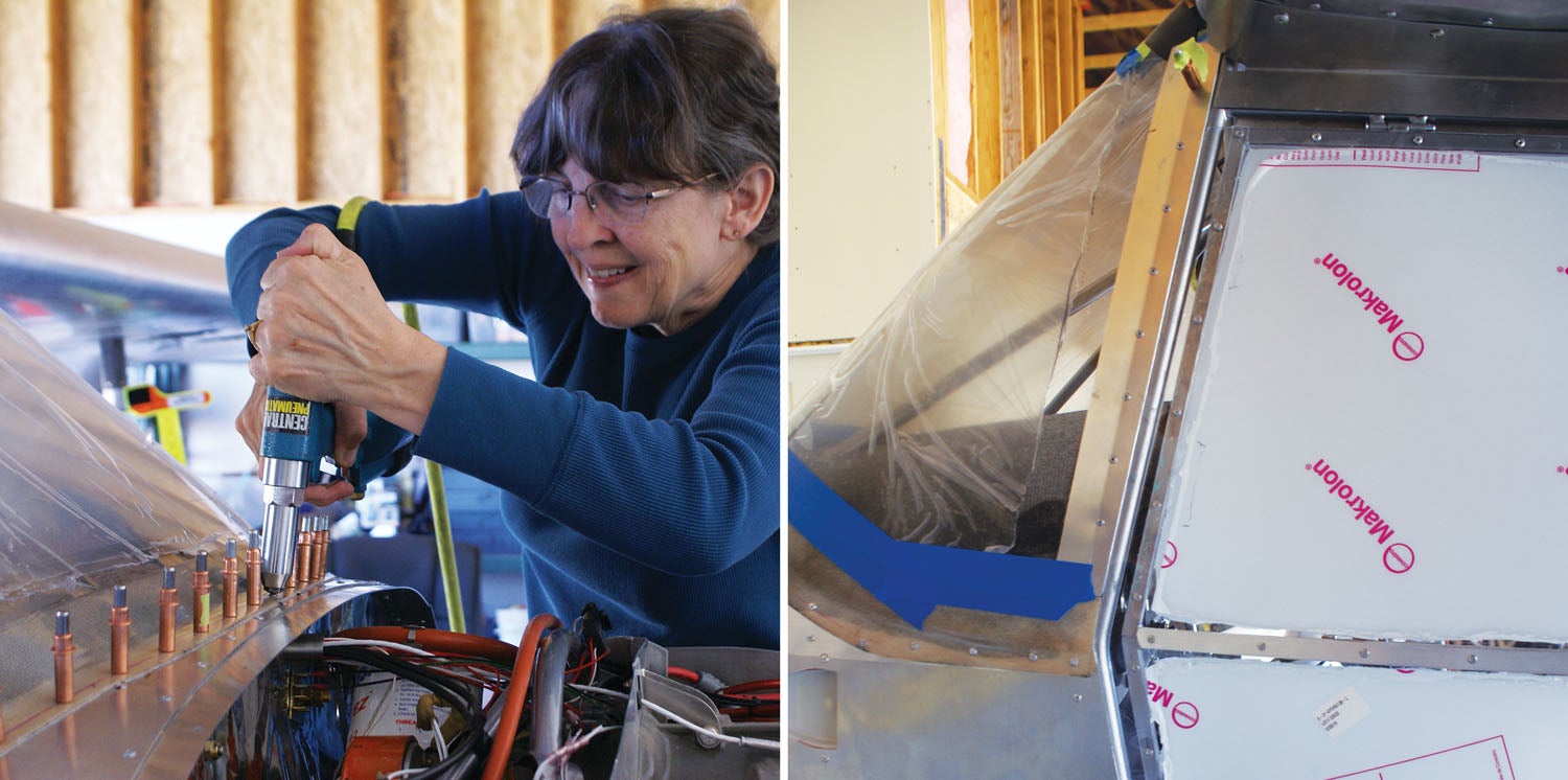
Back to our build, then. Following wiring and avionics, the main project was getting the windshield and skylight installed. We got a bit of a rough start with getting the three ribs “slightly bent” to fit the contour of the main wing airfoil. These ribs are the connecting structure for the windshield/skylight combination. There are three of them (one center and two side ribs) that start at the upper forward part of the steel-tube fuselage structure, where they attach by tabs. They extend aft through the windshield/skylight mating strip area to the aftmost part of the skylight.
The “bending” is tricky, involving many trips up and down ladders by both of us to make sure the ribs were bent just right. One thing that seemed odd to us was that the center rib did not go flush with the windshield toward the very front—a fact not mentioned anywhere in the instructions that we could find. There was no way to change the shape of the tip of the rib. Mike, of course, investigated. After talking to others on the RANS builder site and verifying with Randy Schlitter at RANS, we were satisfied that the center rib was contoured correctly and will not be flush with the windshield at the very front. The center rib is the only place where the acrylic windshield is actually drilled into, so we wanted this to be right.
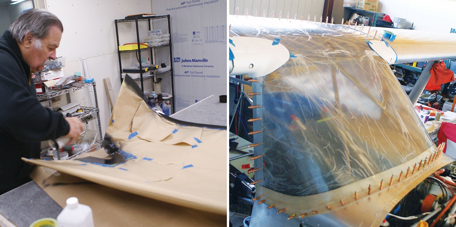
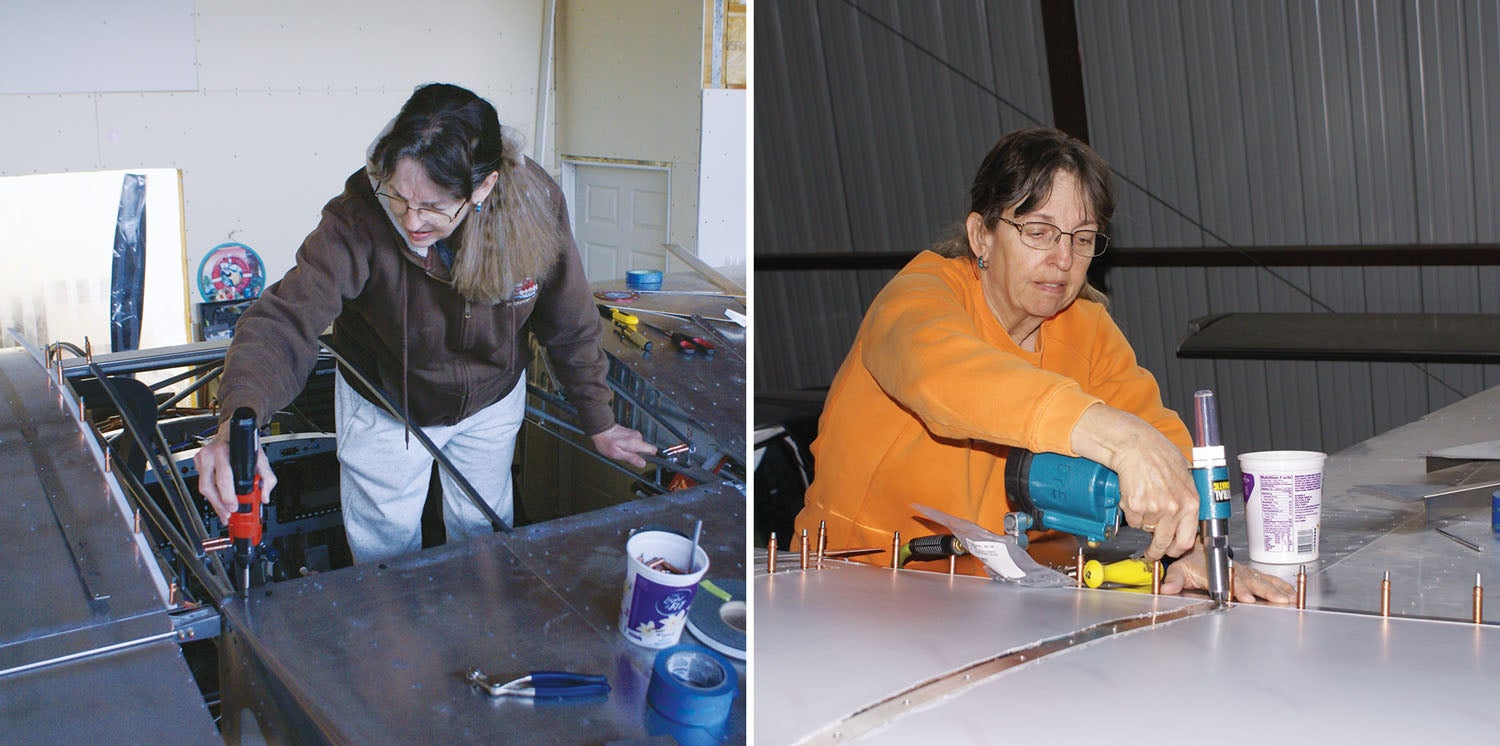
There are many iterations of drilling, deburring and trimming to fit at this stage, so you get used to going up and down the ladder! I found it helpful to have some boards to stand on inside the plane and actually be standing through the roof area to get to some of those hard-to-reach areas. I was amazed that the windshield is held in place with the glued-down windshield hold-down strip that wraps around the base of the windshield to the boot cowl, the spacer strips on the sides, the five screws that go into the center rib on the top and, finally, the mating strip to the skylight. We got all the fitting done but did not do the final gluing of the hold-down strip due to the fact that the special epoxy needed at least 60° F to cure properly. We also held off on riveting the side hold down strips and aft mating strip until after the weather warmed up, which allowed us to take the windshield off, set it aside and continue other projects while waiting for the weather to heat up.
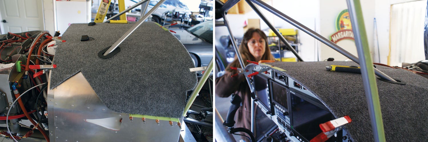
It was now onward toward a bit of beautification. I wanted the dash cover (interior cabin part of the boot cowl) made of a gray indoor/outdoor carpet material for glare reduction purposes, so we went shopping. After going to two carpet stores, we finally decided to check out Home Depot and I found a roll of exactly what I wanted. We cut the piece to fit just inside the windshield, cut a few slits to accommodate the interior diagonal bars and got it glued in place. This is a finishing touch that really looks nice.
Enlisting Assistance
When we had the RV-10, Mike stalled out near the end of the build. (As so many do.) We decided at that time to have one of Mike’s friends, Randy Thorne, come over and help Mike get over the “barriers” he had to finalizing the build. Randy was able to help out several days a week for a few months. This was just what Mike needed at that time to help him over the hump.
We discussed a “Randy visit” to assist Mike with fitting the spinner to the prop, and they both jumped at the opportunity to work together again. (See the sidebar, “Calling Randy” below.)
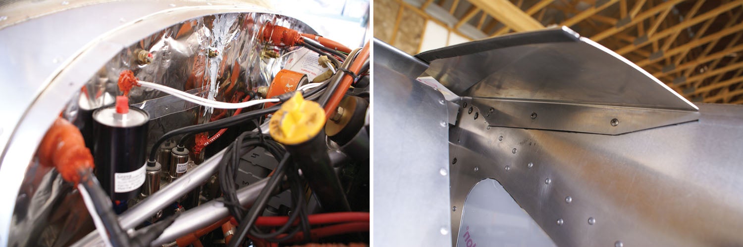
With our decision to go to the constant-speed prop, we decided not to use the 4-inch spacer specified by the factory for a fixed-pitch prop. Our thinking was that the heavier constant-speed prop would move our empty CG farther forward than we wanted using that spacer. The prop is already about 2.5 inches farther forward than the fixed-pitch prop because of the hub’s design, so we decided not to use the spacer. This modification caused ripple effects, requiring Mike a bit of mind-twisting and cogitation time. Mike took the extra length off the cowl at the aft side of the upper and lower cowls to accommodate the prop being closer. Then we had to figure out how to get the air filter in place to fit correctly. I will let Mike describe the magic he did elsewhere (see “Take a Deep Breath” below).
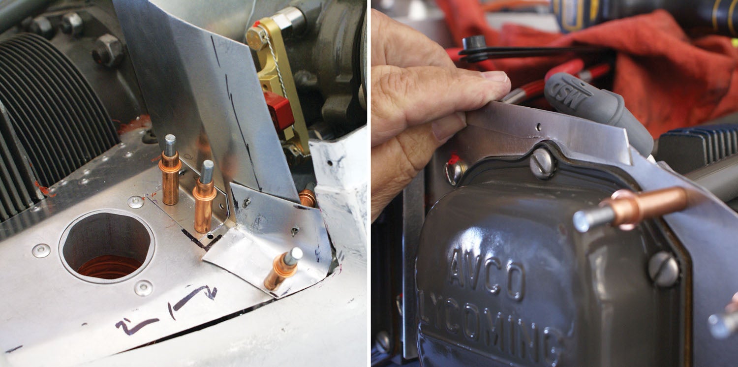
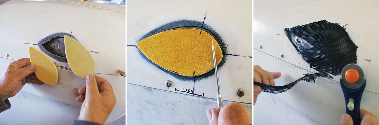
Next, it was time for Mike to address engine cooling. You need to direct the airflow in such a way as to have it circulating around the surfaces of each cylinder without air leaks and details count. As part of his detailing, Mike cleaned up the casting “flash” common in the cylinder-head fins that restricts flow and can make the cylinders run hot. Then he custom fit red silicone material to the fixed engine baffling, a painstaking process that took quite a while. How the cylinder-head temps do during flight will be the true test. While working on the baffling, Mike did some custom fiberglass work to further improve cooling-air flow (see “Building Cooling-Air Ramps” below).
During the process of cowl fitting, Mike noted that the right front cylinder was bumping the inside of the upper cowl. The fix for this was to create a bump in the fiberglass. It’s not a big bump, but I want him to put one on the opposite side to make the airflow symmetrical in flight. It may not make any difference, but mentally I will deal with it much better if it is symmetrical.
Once the weather turned to spring and temps climbed consistently over 60°, it was time for the final gluing in of the windshield hold-down strip and riveting of the side and aft mating strips. With the windshield now firmly in place, we could do the final fitting of the doors, which had been built during downtimes of the build. It was so sweet to get the front edge of the Lexan sanded down to the aft edges of the windshield and boot cowl. I would run my fingernail between the edges, and if it caught where they were touching, we would shave off a bit more. Having two people to put the doors on and off proved to be extremely handy. Mike did several iterations with the handle to get the bushings and washers placed to where the doors pull in for a nice fit.
Propped Up
A crowning moment to this last 90% was the final install of the prop. Our neighbor Paul had recently purchased a fantastic safety-wiring tool (see “The Luxury Tool,” August 2021 KIPLANES®), so we took him up on his offer to assist and invited him over to share this special moment. This tool made the ordinarily difficult job of safety-wiring the propeller a slick and easy job. With the starter ring gear indexed properly, alternator belt secured to the alternator and the O-ring in the propeller, Mike and Paul lifted the prop to get it onto the six bolts. I had never seen a prop hung before, so it was quite the experience to witness this process. We had two of us at a time tightening each side’s bolts (three for each of us), and we would tighten each bolt a bit at a time and switch bolts until the entire prop was securely fastened with all bolts. Then Mike torqued each bolt in three stages—30 foot pounds, then 40, then the final 50.
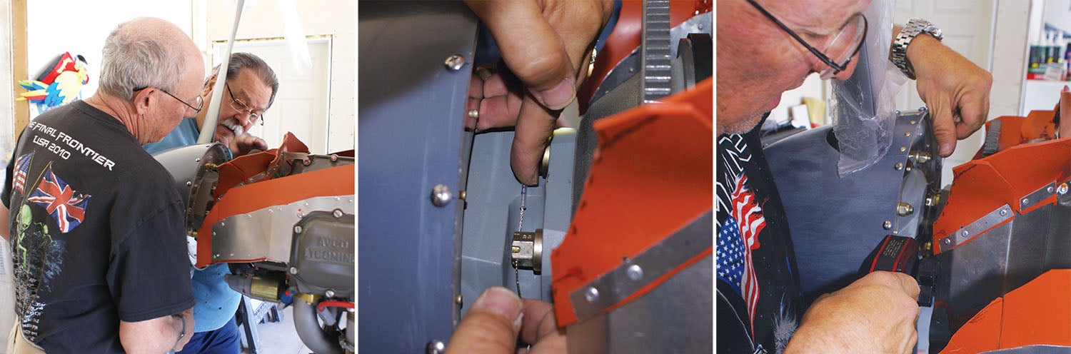
Now came the fun part for Paul, where he could wrap up the job with the safety wiring. He ably wired three sets of two bolts each so that the tension would keep the bolts from backing out. Because this is such a narrow space, Paul’s specialized tool made the job easy. Paul assured me that this was an easy prop hanging, and they do not always go this smoothly. We had the entire job done in about 30 minutes. It is super exciting to see our airplane with the prop on now!
Still More Little Things
Even though hanging the prop is a milestone, it’s also a reminder of all the small things left to do. Such as sealing around the gas caps, sealing the engine side of the firewall with high-temp silicone (specifically Fire Barrier 2000) and then tending to some airframe details. These include setting the aileron cable tension, measuring aileron deflection and setting the control-surface stops, fitting the horizontal-stabilizer gap seal as well as the wing/fuselage gap seal. You get the idea. Looking back on it, I can see the incredible progress we have made. It all needs to be done. Not all of it makes fascinating or even notable reading, but it’s worth stating here that you just need to keep moving, work through your list and get it done. It’s a relief when much on the to-do list is only cosmetic—and many things can be left until after first flight. I am really looking forward to the day that we have the first start of the engine, inspection and first flight.