Potpourri (pronounced “poh’purree”), taken literally from the French origin, is translated “rotten pot.” In English, though, it means a collection of small things; in music a medley of many short tunes; or in writing a series of short subjects. This is a collection of a lot of aviation trinkets, gewgaws and floobydust that, taken individually, would not warrant a full article, but taken together should be of some use to us in the aviation world.
Soldering

Soldering is a form of welding used mostly in electronics, but the temperature is much lower and the filler rod is made of tin and lead (with a central core of rosin to automatically clean the metals to be soldered).
• The most common mix of tin and lead is 60% tin and 40% lead, commonly called 60/40. It melts at 370° F. There is another mix that is slightly less common and that is 63/37. It melts at 361° F and is the lowest melting temperature (called “eutectic”) of any tin/lead combination. The most common size of either mix of solder used in electronics is 0.031-inch diameter. Soldering large pieces together may be easier using 0.050-inch diameter, but this size is not used for “delicate” soldering (like PC boards and connectors).
• The difference between 60/40 and 63/37 is that 9° difference in melting temperature. In that 9° difference, 60/40 melts at 370° but it doesn’t completely solidify until 361°. In that 9°, the solder is actually “plastic” and if jiggled the slightest bit will solidify with cracks in it that will break off the joint when solid—the properly named “cold joint.” There’s no plastic range for 63/37. It goes directly from molten to solid, with practically zero chance for a cold joint. The cost for 60/40 is about $30 for a 1-pound roll while 63/37 goes for $40 for a 1-pound roll.
• If your application calls for real mechanical strength, the addition of 2% silver to the tin/lead alloy has a eutectic melting/solid temperature of 354° F, and you can expect to pay $5 or so more for a roll of “silver solder.”
• Cheap tool—the cheapest in your toolbox. Solder is soft. Most of us just roll a few yards off of the big 1-pound roll and wind it into a “hank” around the fat part of our hand. It is somewhat unwieldy and tends to tangle. In general it’s a clumsy way of handling solder. Get a 12- or 16-penny sinker nail (the kind with the brownish-greenish mottled finish). The coating is actually a mild glue that melts and binds wood to wood when struck with a hammer. It is also mildly sticky. Grind the nail point off so you don’t stab yourself. Wind the solder on the nail and hold it in the palm of your hand and the solder exiting between the first and second finger. Make a fist to hold the nail-solder. Unwind the solder as you use it.
• Variable temperature soldering station. Expect to spend $100 or so for a good one. Don’t buy any extra tips; tips last forever. A good soldering gun is good for very heavy soldering jobs. Don’t even think about using a gun on a PC board.
• The soldering station comes with a sponge that you wet to wipe old solder from the iron tip. Throw the sponge away and get some brass shavings from the hardware store. Much better than a sponge to wipe the iron tip.
• Buy a couple of wheels of desoldering braid, which is nothing but copper braid that has been soaked in flux. The braid will soak up the solder on a joint, allowing you to remove a component from a PC board or other solder joint.
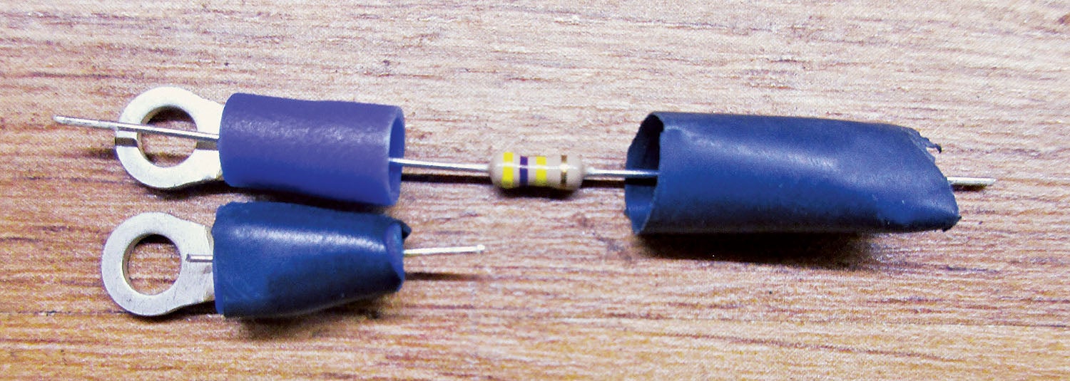
The 10¢ Static Wick
Some aircraft go fast enough to generate static electricity, which shows up as noise in your com and nav radios. Static jumps from the airframe to the air on the sharpest corners of the airframe. The idea is to discharge the energy of this static electricity by forcing the electricity to get to a very sharp point through a resistor that absorbs all that energy. Get one crimp terminal, one 100 kΩ ¼-watt resistor and one short length of shrink sleeving. Bolt to a sharp metal surface. The sharp point can be made by a wire cutter on the resistor lead (good), a short lead of one wire taken from a multi-lead hookup wire soldered (better) or the sharp end of a pin soldered from the family sewing chest (best).
The $10 Glideslope Splitter
This one is going to save you big bucks. Short theory: antennas are generally based on the “quarter-wave” principle. That’s the way you make antennas a quarter-wave long. Almost. It is based on the “odd multiple” of quarter-wave. That is, if an antenna is good at 110 MHz with a quarter-wave element, it is also good at 3x (and 5x and so on) that frequency. Guess what? The glideslope frequency is almost perfectly centered on the “3rd harmonic” of the 110 MHz LOC band at 330 MHz, right in the middle of the glideslope band. Yup, your good VOR/LOC antenna is also “resonant” (good) at the glideslope band. The problem is to couple off the glideslope signal without affecting the VOR/LOC signal.
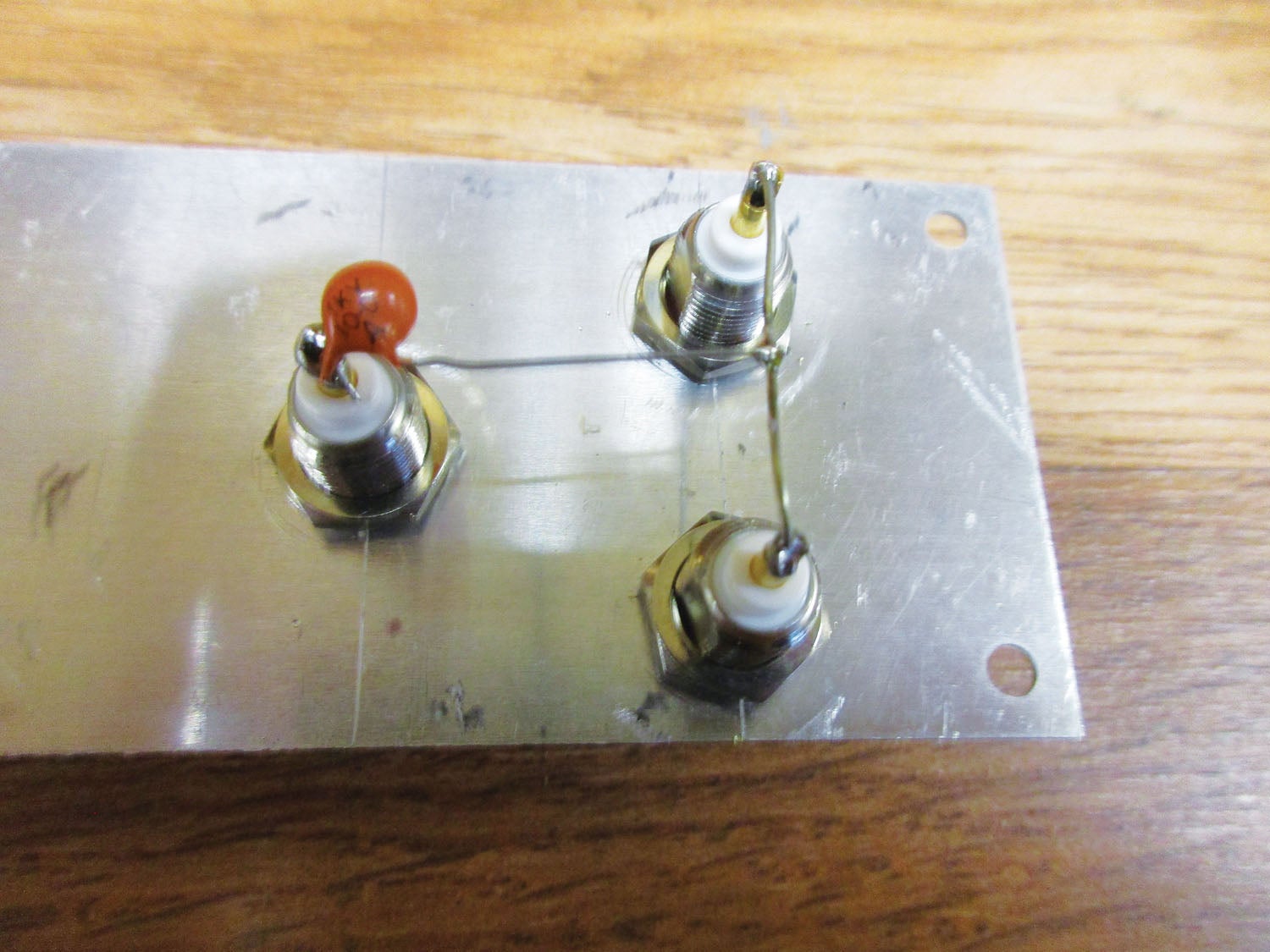
• Permit me a bit of RF hand-waving. A capacitor (two conductors separated by an insulator) and an inductor (a “coil” of wire) connected in series is a direct RF short to radio signals at one—and only one—frequency. (Aside, connected in parallel, they are a direct open to radio signals at the same frequency). So, the problem is to get a series LC (inductor-capacitor) circuit to couple off the glideslope frequency without bothering the VOR/LOC signal.
• It’s also true that a straight wire has an inductance, no matter how small (measured in nanohenries—billionths of a henry), of 25 nH per inch. It turns out that a 10-picofarad capacitor with one-inch leads is resonant at 330 MHz with a 25-nH inductor. Bingo. A single 10-pf capacitor with 1-inch leads (1/2 inch per side) couples off the glideslope signal from the nav antenna with nearly zero signal loss to either the VOR or LOC signals.
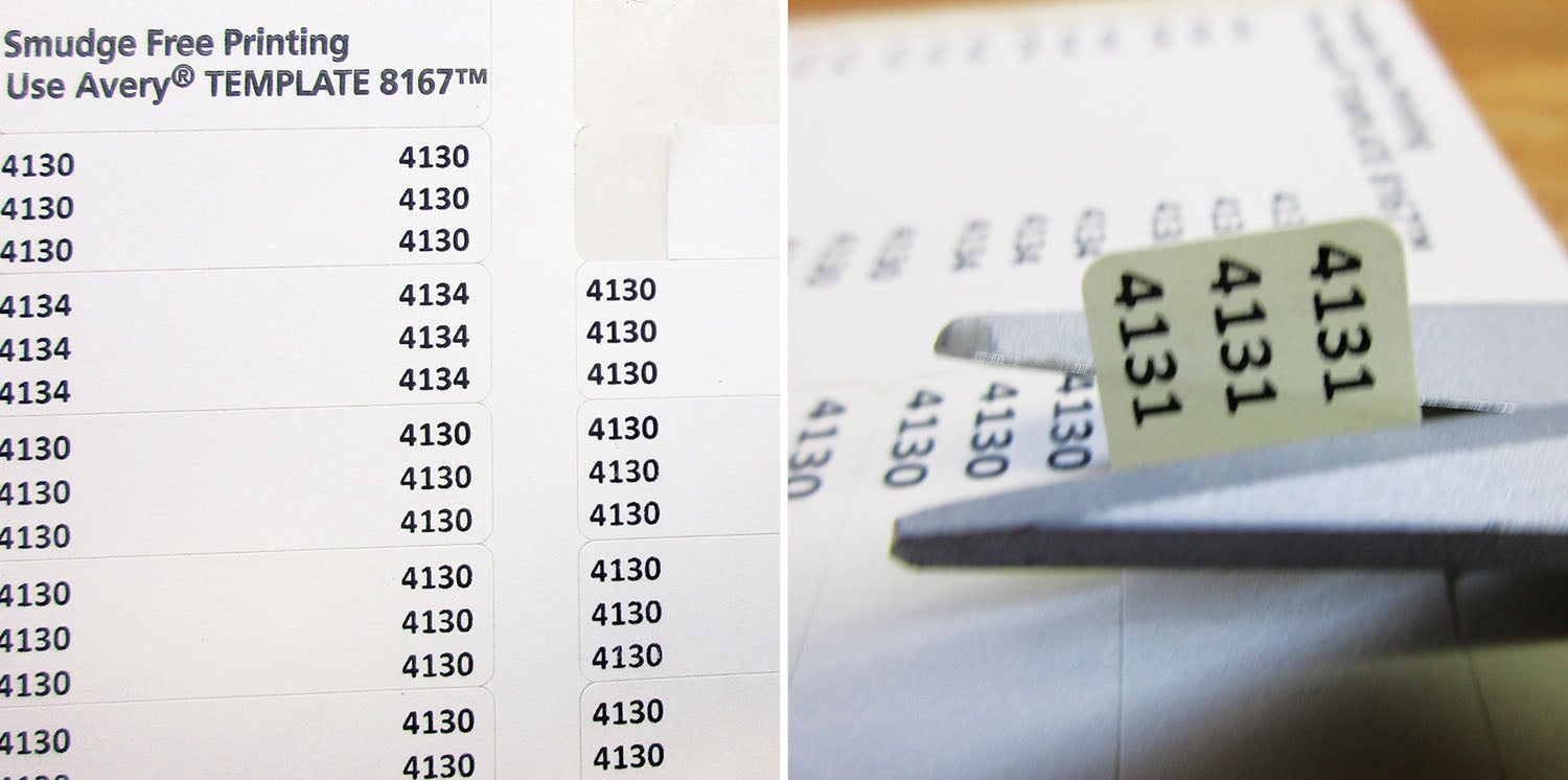
Wire Marking for a Nickel
We covered this one pretty well back in the September 2009 issue of Kitplanes®; it has been over a dozen years since we have revisited the idea, and I have some recent data that will reinforce what we said way back during the first year of the Obama presidency.

Most of these systems that we discussed involved putting characters on some sort of sticky-back label, wrapping the label around the wire and covering it with shrink sleeving. I have some emails from the ensuing years that tried the marking system using “permanent marker” colors and others that used inkjet and ink printers. Notably there was 100% failure of these trial systems (contamination of the label or solvent leakage onto the wire), but 100% success of builders that used laser printers (color and b/w) to print the labels.
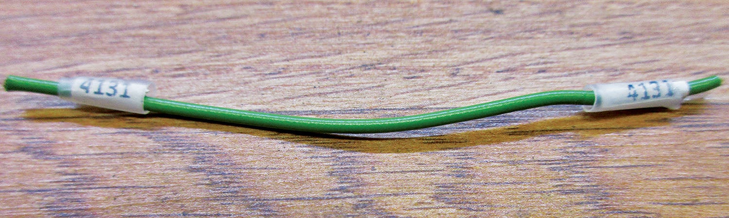
• Here is the deal in a nutshell: Each wire in the aircraft is assigned a number (see the table). There is a wire identification number for that wire in accordance with the table. You print the number on a sticky-back label from the stationery store (Avery Label) using the smallest label you can get (generally a return address label) on a laser printer.You print two copies of this label, one for end A of the wire and one for end B. You put the label on the wire(s) so you can read the number. You shrink clear sleeving over the label. You record the number on a spreadsheet of some sort that tells what the wire does—Do not skip this last step.
• There is computer help to make lots of sequential labels (i.e., 4013, 4014, etc.) in Microsoft Word. This is one of the best.
• Yes, it takes a hell of a long time to do this. Yes, it takes a quadruple hell of a long time to troubleshoot the electrical system without this sort of roadmap.
We’ve got a real chance of finishing up our HOG system before the bad Sierra winter weather sets in (or the California fires burn the place down), so stick with us. I’ve got a dozen more of these floobydust subjects for next year. Until then…Stay tuned…


