In an article in the December 2015 issue of KITPLANES [“Stressing Structure: Tubes, Struts, and Column Buckling“], we discussed column buckling and looked at Euler’s equation. Column buckling is what happens when a long skinny pushrod or strut or something like that is put into compression; if the load is large enough and the structure skinny enough, it’ll eventually buckle. When that happens it bends out of column. While Euler buckling is elastic, the stresses due to both the compression and the bending can easily become high enough that the structure takes a permanent set. Locally there, the structure has become plastic. It might even go past plastic behavior and fail, although even the buckling itself is often a failure—think of a wing strut collapsing.
There’s a variation to this that’s very important with aircraft design. It’s called beam-column buckling. This is buckling due to the exaggerated bending that happens when there’s both a side load and the compression load. It affects things like spars inboard of strut attachments, struts themselves, and even long pushrods. The side loads are usually things like air loads or gravity loads or drag or lift forces. Sometimes a part that carries compression is designed to go around something else, and that bit of offset causes bending in the part.
Many different loading cases have been worked out for different combinations of end conditions. You can find a number of these in the Bell Structural Design Manual starting on page 847 in the PDF or on page 11-72 as numbered in the manual.
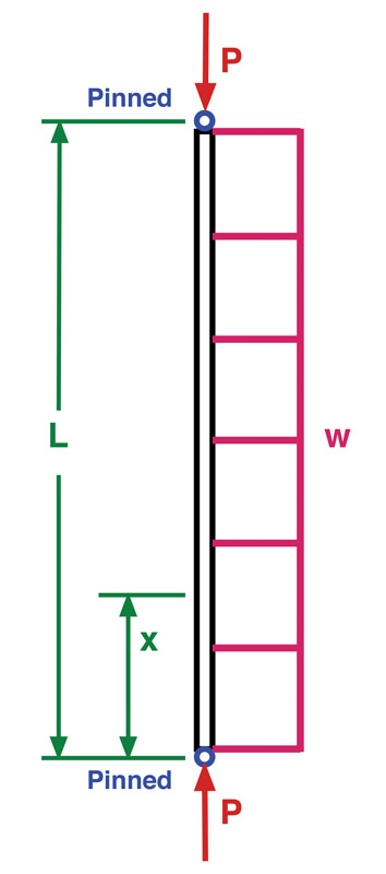
For an example, we’ll use one of the more common instances of this sort of load. The drawing shows a strut. It’s pin-ended on both ends, it has a constant cross section with a symmetric and stable shape, and it is made of just one material. It has an axial load and a uniform side-load.
The main symbols are:
L – Length from one rod-end bearing center to the other one, inches.
x – Distance along the length where the bending moment will be calculated, inches.
P – Axial load, pounds force, always positive even in compression.
w – Uniform side-load, pounds force per inch.
M – Moment calculated with this technique, inch-pounds force.
Mo – Moment calculated as if there were no axial force to deal with, inch-pounds force.
E – Modulus of elasticity (that is, Young’s modulus) for the strut material, psi.
I – Area moment of inertia of the strut cross-section, inches4.
This particular load case is shown in the reference as the third item in Table 11.3.
There’s lots of math involved with beam columns. None of it’s hard, but you’ll need a scientific calculator that can handle trig functions using radians for the angles. With beam-column analysis, we never use degrees, and there’s a good reason for that, which I’ll cover later in the article. Also, and this is an exception to the general rule that we only really need three significant figures in our analysis, here we need at least four, and often five are appropriate. Remember that significant figures are counted from the most significant digit, the left-most one, to the least significant digit, the right-most one, regardless of where the decimal point falls. Most calculators will automatically use as many significant digits as they can handle and only show what you ask of them, so in general, calculators or spreadsheets or Mathcad are acceptable analysis tools for this.
Normally in aircraft analysis, the factors of safety are applied to the final result in analysis. In beam-column analysis, though, they are used immediately in the loads in the equations. This is because beam-column analysis is highly non-linear and is very sensitive to the magnitude of the load. A factor of safety of 150% might create a critically important result, showing that the column would actually fail, where if you’d used that same factor of safety on the final bending moment, it might have erroneously looked acceptable.
Finally, there’s a caveat in the Bell Structural Manual that I hadn’t noticed in other manuals. Bell says that when the bending moment that you calculate with this technique is within 1.1 of the bending moment that you would calculate if you ignored the axial load, this technique is inaccurate. That is, if
M / Mo ≤ 1.1
then the equations aren’t accurate. I’ll discuss that later, too.
There are a number of different little things to calculate. We’ll do that first and then dive into the big equation.
j = [ E • I / P ]1/2
This has units of length. This equation is why P is always positive: we can’t take the square root of a negative number.
C1 = w • j2 • ( [ cos ( L / j ) – 1 ] / sin ( L / j ))
This has units of bending moment.
C2 = – w • j2
This has units of bending moment.
f (w) = w • j2
This has units of bending moment.
The various different types of load or end constraint have different equations for C1, C2 or f (w), and you’ll need to see the table in the Bell manual for those. This example uses these equations.
M = C1 • sin ( x / j ) + C2 • cos ( x / j ) + f(w)
The bending moment M is the moment at any point x along the length of the column. By varying x in the calculations, you can calculate the full moment curve, and if you have a load that’s not symmetric about the center of the beam column, you’ll have to do that to find the location and magnitude of the peak bending moment. An example of such a load is the spar inboard of the strut, on a Cub-like aircraft. It has a more-or-less uniform load, but also has a bending moment applied at the spar at the strut attachment from the outer portion of the wing spar, outboard of the strut. There might be a moment at the root or not, depending on the orientation of the inboard spar fittings, and that sort of detail will vary from design to design.
A shortcut to the maximum moment is
Mmax = [ C12 + C22 ]1/2 + f(w)
Since there are two roots of the first term, use the one that matches the sign of C1. This isn’t obvious, but the equation works if you do this; this tip was from one of the references.
Incidentally, you can combine different load cases from the table in the Bell manual, but you have to use the full axial force on each one, and the combined maximum bending moment will still need to be determined.
For this particular load case, the maximum bending moment is in the middle and is found using this equation from Bell’s table, which is specific to this particular load case:
Mmax = w • j2 • [ 1 – sec ( L / ( 2 • j ) ) ]
My calculator doesn’t have a secant button, but there’s an easy work-around:
sec ( n ) = 1 / cos ( n )
for any number n.
This can be compared to the moment calculated as if there were no beam-column effects to see if the beam-column equations are accurate, per Bell’s warning. Bell doesn’t say what to do if the numbers fall in the inaccurate range so you’re on your own there. However, the basic beam-column equations were developed by Niles and Newell, and in their book, they don’t mention this issue. I’d be inclined to use whichever bending moment is highest, along with a special factor of safety of 1.1 in this situation, and that would be conservative.
Being conservative in engineering isn’t a political thing—it has to do with the need to keep on the safety side of things. It’s OK to have something be slightly too strong. It’s not OK to have something fail. So we bias our work to ensure than any uncertainty will not cause a failure—and that’s being conservative. And with buckling, a bit of extra conservatism is almost always worthwhile. Remember that the factor of safety applies to the forces used when you start these calculations.
Earlier, I mentioned that only radians are to be used in beam-column analysis. The reason for this is that in the derivation of the theory, a mathematical concept called a “series expansion” is used. We don’t need to go into that type of math here, and it’s entirely unnecessary to know about it to use these techniques. But it turns out that trig functions can also be described as a form of series, and since trig functions can easily be applied by a working engineer, Niles and Newell adopted them for this analysis. As a result, in spite of using trigonometry in the equations, there are no actual angles involved.
If you’re interested in the development of the theory, you can look up Airplane Structures, Second Edition, Volume 2 by Alfred S. Niles and Joseph S. Newell. Published in 1938, it’s quite a readable book, oriented towards the working engineer.
If you’re doing this analysis on something like a spar, don’t ignore the loads perpendicular to the major loading. The perpendicular load might be small, but the cross-section will be too, and even if the lengths between major supports—usually the compression struts—may be closer than the distance between strut attachment and the spar root, it’s definitely worth a check. One interesting thing about the beam column bending in this direction is that since the ribs usually connect the two spars (if there are two spars), it’s probably best to consider the spars acting together.
Likewise, on streamlined wing struts, check both directions. The drag is generally aligned reasonably well with one axis, but the lift is mostly applied to the other axis, and at high angles of attack during compression loadings, might become important.
If a beam column is in tension rather than compression, the effect tends to reduce the bending moment. The Bell manual includes equations for these load cases, and they use the hyperbolic trigonometric terms. These are written like “sinh” or “cosh.” Since these are a bit harder to use for that reason, and because most stress engineers would rather be a bit conservative rather than a bit precise, these are rarely used in actual classical hand analysis. On the other hand, if you’re using hand analysis techniques to check the results of a computerized finite element buckling analysis (always worth doing), then it’s worth knowing that these are available and can be applied—as they should be in that case.
If you do need these hyperbolic trigonometric functions, please refer to wikibooks.org for a clear set of equations.
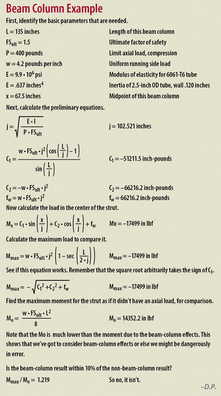
The sidebar shows the analysis of a rather rugged strut. It doesn’t actually apply to any particular airplane and especially it might not apply to yours. It’s only an example. It uses the third case from table 11.3 in Bell.

