So far we’ve talked about polarization, copper tape, dipoles, ground planes, and the like. Now we come to those parts that pipe your signal to and from the antenna to the radio. We call them transmission lines. All transmission lines have what is called a “characteristic impedance,” and unfortunately for us to comprehend, this impedance is measured in ohms.
At first, you might think that you could just take your trusty Harbor Freight multimeter, put it on the ohms scale, and measure the impedance of your transmission line. Nope, doesn’t work that way. Impedance (in ohms) and resistance (in ohms) are two totally different animals. Strange to say that the only real way we have of measuring a transmission line is to put a signal in one end and see how much is left at the other end.
There are a couple of dozen ways of making transmission lines, but the main one for aircraft use is coaxial cable, commonly referred to as coax, and overwhelmingly we use 50-ohm cable. As I said in a prior article [“Three to Get Ready,” September 2018], 70-ohm coax has minimum loss while 30-ohm cable has maximum power capability. 50 ohms is a compromise between these two and was chosen in the first place during WW-II as what could be made out of British standard copper plumbing pipe.
Those of you who have the shivering timbers when remembering Algebra II in high school can skip the next two paragraphs. We are going to be talking about decibels (dB). Any transmission cable you use is going to have a certain loss, and we measure that loss in dB. Since we can’t gain power in a simple coax wire, this will always be a negative number. For example, if I put in a watt of power and only have half a watt at the other end of the line, we say we have a -3 dB loss. To put it in math format, dB = 10 log P1/P2. P1 is the power at the output end, and P2 is the power at the transmit end. Try using that completely virgin “log” button on your calculator, and prove to yourself that half power is -3 dB (actually 3.010 if you carry it out for 3 decimal places).
But what does all that mean in the real world? Let’s compare two coax types and see. How about we use the middle of the VHF nav/com band (it won’t vary much from one end to the other) at about 120 MHz. And let’s do it for a one-foot length. You can get the exact number for your installation by multiplying by the number of feet in your cable run. Using RG-58 and the calculator at https://tinyurl.com/coax-calculator, we find that at the end of that foot of coax, you will have lost 0.05 dB, or about 1% of your signal. If instead you choose to use the little tiny RG-174, you will increase the loss to 0.1 dB and about 2% of your power. A 6-foot run of coax? Just multiply the numbers above by 6.
How about at the transponder frequency of about 1050 MHz? Those per-foot losses for RG-58 jump up to 0.17 dB and 4%, while RG-174 loses 0.35 dB and 8% of signal. However, now a secondary matter rears its head: RG-58 can handle 200-watt peak pulses of power, but RG-174 will not handle more than about 50 watts. My coax of choice for the transponder is and always has been RG-58.
Let’s jump up a bit to the GPS frequency of 1525 MHz. RG-58 loses 0.25 dB per foot, which translates to a 5% signal loss while RG-174 tops out at half a dB (0.50 dB) and 10% loss of power. But wait a minute—some of the GPS/ADS-B machines require a loss of around 5 dB, which you can get with a 10-foot run of RG-174 that weighs about 4 ounces. Using the recommended RG-400, you will need roughly 30 feet of cable that weighs about 2 pounds. Not to mention finding space to coil up all that excess cable.
Conclusion: For powers less than 50 watts, my cable of choice (if loss is desired or not a factor) is good old RG-174. But when it comes to powers greater than this, I’ll go with RG-58. RG-400 isn’t even in the picture.
One more little item and we can get on to a couple of neat things to do with coax other than just running from radio to antenna. But to do that, we need to discuss that polyethylene “dielectric” insulator between the center conductor and the shield. Running signals through that dielectric has the same effect on the signals that you experience running through deep water. Neither you or the signal can go as fast in thick water or polyethylene as you can in thin air. How much slower? For polyethylene, the signal will go at 66% of the speed that it goes through air: 186,282 miles per second in air is 122,946 miles per second in polyethylene.
Why is this important? Because we are going to go back to that thing we learned last month about calculating how long a quarter-wavelength is. For our first trick, let’s do the calculation for the middle of the VOR/LOC band at 113 MHz: 122,946 mps divided by 113 million cycles per second gives us a wavelength of 0.0010880 miles times 5280 gives us 5.74 feet times 12 gives us 68.9 inches for wavelength. Divided by 4 gives us 17.25 inches for a quarter-wave in coax with polyethylene dielectric (which is used for both RG-58 and RG-174).
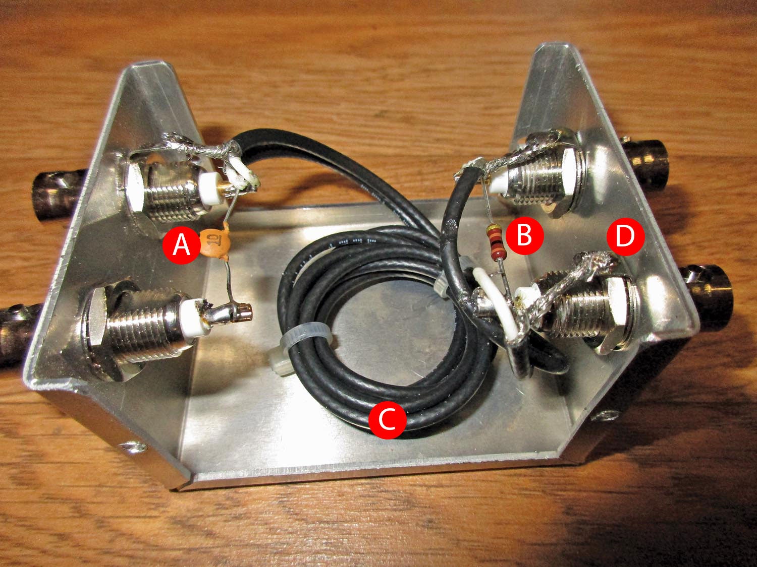
Power Splitter/Combiner
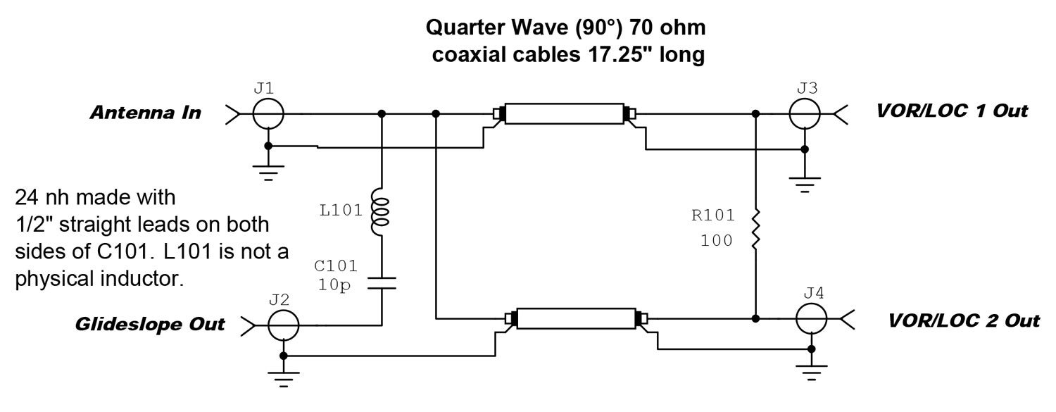
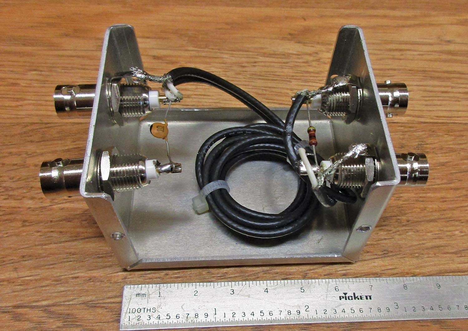
A pretty smart fellow named Wilkinson designed a power splitter/combiner using quarter-wave sections of coax and a single resistor. I’ve shown how to use it with BNC connectors. You can use it with connectors of your own desire. One thing that may not be too obvious is how the glideslope is coupled off. It turns out that a round, straight wire has a self-inductance of about 24 nanohenries per inch, and it doesn’t vary too much across a relatively wide range of wire sizes. A series circuit made from a 1-inch piece of wire and a 10-picofarad (pF) capacitor makes a series resonant circuit in the middle of the glideslope band and couples the glideslope signal off of the antenna.
You may ask yourself how you can get a glideslope signal (at 330 MHz or so) from an antenna cut for the VOR/LOC band down at around 110 MHz. I didn’t tell you the whole truth, so here it is: I said that a quarter-wave antenna is resonant, but it is also true that a three-quarter-wave antenna is also resonant, as is every odd multiple of a quarter-wave. Guess what? A quarter wave at 110 MHz is also resonant at three times that frequency or 330 MHz (and 550 MHz, and 770 MHz, and so on).
You may also ask yourself about that comment on the schematic about using 70-ohm coax when I told you never to use 70-ohm coax. Again, I didn’t tell you the whole truth. For very special things like this, we can bend the rule because it just works better this way.

Two caveats and we’ll wind up this month: One is that you can use this for combining two signals into a single antenna, but you cannot couple two transmitters this way. And, that little 100Ω resistor is a tiny little thing with short leads; I generally use a quarter-watt carbon film resistor with good results.
Next month might be my Oshkosh special column for all the new stuff I saw this year, or if that doesn’t get done in time (my deadline is the week I get home from Oshkosh), I may go into some really neat ways of using your newfound knowledge about transmission lines, quarter-wave, and all that stuff. In any case, until then…Stay tuned…


