
With the recent rush to ADS-B, there has been a significant interest in GPS installations and even more interest in the antenna for those GPS installations. The interest runs the gamut from the eBay $1.99 specials to the gold-plated TSO-STC-PMA antennas, some of which are in the popular aviation catalogs ticking the $1,000 mark.
The question is…how do I know which one I really need? With a thousand bucks in the balance, which one will do my job?
To answer the question, we need to know a few things. First of all, does my GPS receiver need a “gain” antenna, and if so, how much? Second, does my GPS antenna need some sort of metal “ground plane,” and if so, how much? Finally, we need to know a little bit about the characteristic of the GPS signal itself.

Your receiver’s data sheet should tell you something about the antenna requirements for your GPS. For example, the Appareo ESG manual on Page 19 says that the antenna needs to have a gain of about 30 dB (see next paragraph), but the coax cable in between the antenna and the GPS needs to have at least 2 and no more than 7 dB of loss. One thing worth noting is that some manufacturers specify very low loss (expensive) RG-400 cable and then go on to say that you need at least 10 feet and no more than 30 feet of this low-loss cable. If you use much less expensive good old RG-174, you can cut these lengths in half and cut the weight from about 2 pounds to 2 ounces. In the November 2019 issue of KITPLANES®, we said that RG-58 was good for almost every aircraft use other than using RG-174 for the GPS if we need to introduce some loss.
Also in the November issue, we introduced the concept of “decibel.” Let’s take a little better look at it, starting with some history. Alex Bell needed a way of measuring “loudness” in his new-fangled telephone system, and he also knew that the sound pressure on the ear was not linear—doubling the sound power did not double the perceived loudness. He actually found that the ear responded logarithmically to sound pressure, so he came up with the definition of the bel. It’s calculated as logarithm of the two powers, or in math format, bel = log P2 / P1. Later, the sound engineers Fletcher and Munson found the bel way too big to use, so they divvied it up by a factor of 10, giving us the decibel, which they shortened to “dB.” Thus, dB = 10 log P2 / P1. And since sound power is proportional to the voltage squared, dB = 20 log V2 / V1 where V is the voltage that is producing the power.
If you go through this little exercise (you might just play with it on your hand calculator), you’ll find that this 30 dB antenna requirement says that the power received by the antenna will be amplified by a factor of 1000, which is a voltage gain of 31.6. (i.e., (31.6)2 = 1000).
Not to blow your mind too much, we find that a dB measurement can be negative as well as positive. In the coax discussion above, the coax needs to have at least -2 dB and no more than -7 dB of loss. Hands on the calculator says that this is a power loss of about 37% to 80% of the available power, which translates to a voltage loss of about 21% to 58%.
There are a couple of other decibel measurements we should cover, and then we can start talking about the two antennas we are going to compare. There is the dBm, which is a power measurement using one milliwatt (the “m”) as the reference. And there is the dBi, which is the gain (or loss) of an antenna relative to an “isotropic” antenna. An isotropic antenna is a figment of our imagination, as it is an antenna with zero physical elements radiating power equally in all directions. It’s a physical impossibility, but mathematically it’s possible.
Now, the absolute minimum signal that a satellite will deliver to the earth is -135 dBm, which is a horribly small signal of about 0.04 microvolts (0.00000004 volts). However, if we use an antenna with 30 dBi of gain, we will see just about 1 microvolt (µV) of signal at the GPS. If we realize that most of our com radios deliver a perfectly good (but somewhat scratchy) voice level in our headphones with an input of 1 µV, we see that this signal is usable by the GPS for navigation.
| Coaxial Cable Comparison | |||
|---|---|---|---|
| RG-174 | RG-400 | RG-58 | |
| Loss at 1.5 GHz dB/foot | 0.37 | 0.19 | 0.28 |
| Length for 2 dB (feet) | 5.4 | 10.5 | 7.1 |
| Length for 7 dB (feet) | 18.9 | 36.8 | 25 |
| Weight (ounces/foot) | 0.13 | 0.736 | 0.4 |
| Weight for 2 dB (ounces) | 0.7 | 7.4 | 4 |
| Weight for 7 dB (ounces) | 2.5 | 27.2 | 10 |
Types of coaxial cable suitable for aircraft use.
| Antenna Comparison | ||
|---|---|---|
| Tess | Joe | |
| Gain, antenna plus low noise amplifier (dBi) | 33 | 34 |
| Axial ratio (dB) | 2 | 3 |
| VSWR (:1) | 1.5 | 1.5 |
| Lightning protection | Yes | Yes |
| Waterproof and hermetically sealed | Yes | Yes |
| Output provision | TNC (F) Connector | 5 meter RG-174 coax |
| Working voltage (DC volts) | 2.5 – 5.5 | 2.5 – 5.5 |
| Operating temperature range (°C) | -55 to +85 | -40 to +85 |
| Polarization | RHCP | RHCP |
| Size (mm length x width x height) | 75 x 120 x 18 | 60 diameter x 38 |
| Weight | 200g | 125g |
| Metal ground plane necessary | No | No |
| Meet TSO-C144 | Yes-marked | Yes |
| Street price | $250 | $80 |
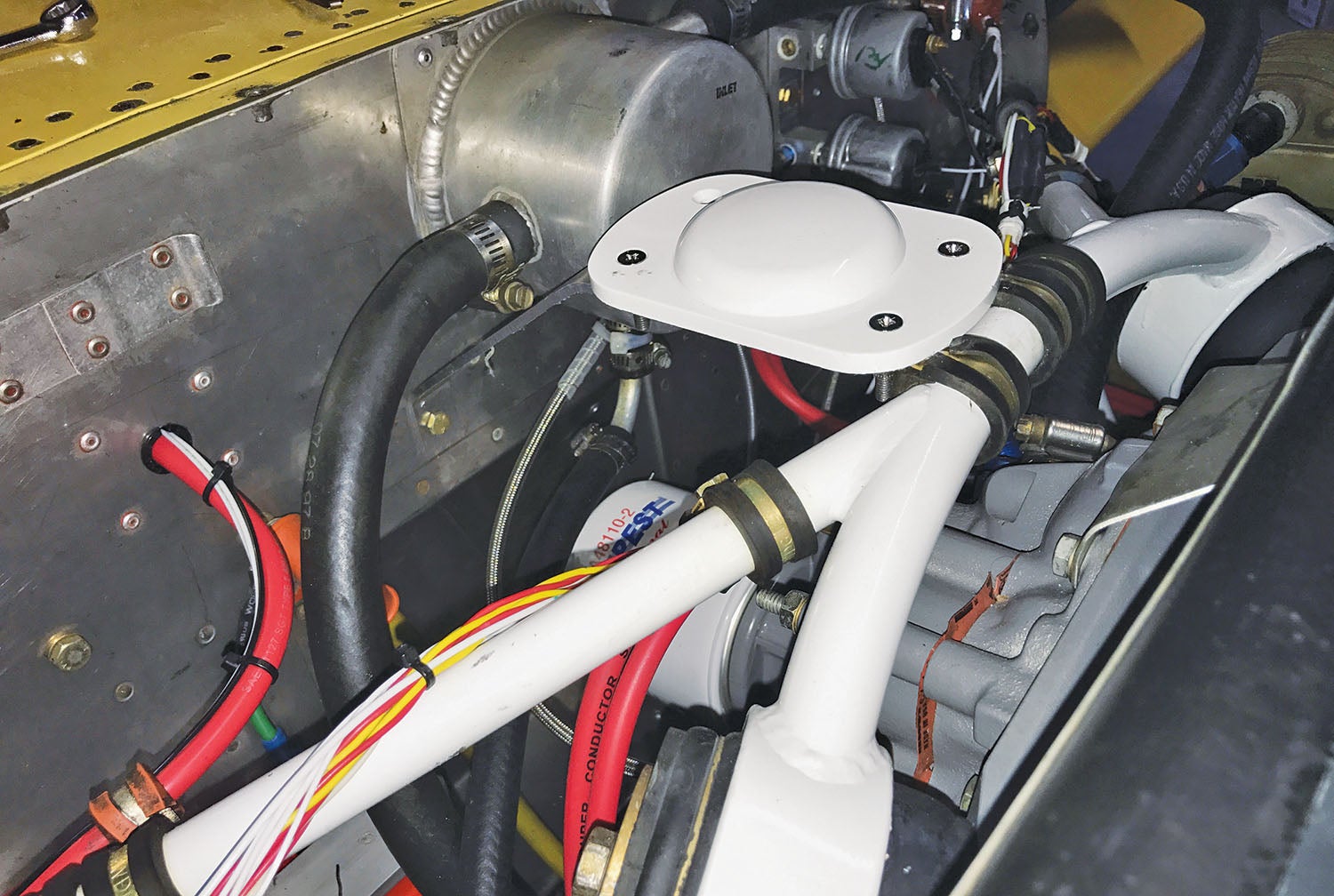
Tess is the standard antenna that comes with one model of popular GPS, and Joe is an aftermarket antenna.
So, let’s compare the two antennas. I will not use trade names, but we can nickname the antennas Tess and Joe if you like (“…the rain is Tess, the fire is Joe, and they call the wind Maria.”) Refer to the chart showing the comparison. Tess is the standard antenna that comes with one model of popular GPS, and Joe is an aftermarket antenna.
Tess has a gain of 33 dBi. Joe has a gain of 34 dBi. To me, a difference of 1 dB is inconsequential.
Tess has an axial ratio of 2 dB. Joe has an axial ratio of 3 dB. Axial ratio in its simplest form is how much does the antenna pattern vary from a perfect circle at the worst point. Again, 1 dB isn’t a significant factor.
Tess and Joe have identical VSWR (Voltage Standing Wave Ratio) numbers of 1.5:1. VSWR is a measure of how well the antennas are matched to the 50Ω coax cable.
Tess and Joe both have the shield of the coaxial cable attached to the metal frame for lightning protection.
Tess and Joe are both waterproof and hermetically sealed.
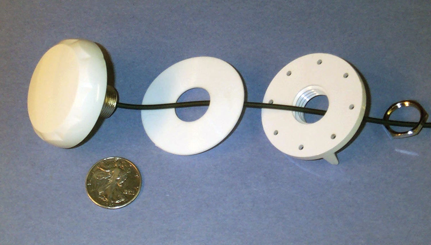
Tess has a TNC output connector. Joe has a 5-meter length of RG-174 cable permanently attached.
Tess and Joe both work from 2.5 to 5.5 volts DC supplied by the GPS receiver.
Tess works from -55° to +85° C. Joe works from -40° to +85° C. I don’t plan on flying in -40° C weather, so it doesn’t make a difference to me. Then again, I don’t live in Minnesota.
Both Tess and Joe use right-hand circular polarization. This is an absolute must, as this is the polarization that the GPS satellite is compatible with.
Tess is 75mm x 120mm x 18mm and weighs 200 grams. Joe is 60mm in diameter x 38mm high and weighs 125 grams. Tess needs a ½-inch hole for the connector and four #10 screw mounting holes. Joe needs a single 7/8-inch diameter mounting hole.
Both Tess and Joe will work without metal ground planes and through fiberglass. Both Tess and Joe work marginally better with a ground plane, but it is hardly measurable.
Both Tess and Joe meet the requirements of TSO-C144. Tess is so marked. Joe is not.
Tess is about $250 on the open market. Joe is about $80.
My money is on Joe, but Tess may be your choice if you need the bottom end temperature range.
So, where from here? I’m going to take you on a guided tour of the design of a modern audio panel, and then I’m going to let you take a survey to see just what you think is important. Until then…Stay tuned…
![[Credit: JetStream Rider]](https://www.kitplanes.com/wp-content/uploads/2026/04/AdobeStock_345999332.jpg?w=218&h=150&crop=1 "2026 Avionics and Lights Buyer’s Guide")
![[Credit: Dynon]](https://www.kitplanes.com/wp-content/uploads/2026/04/EMS-stand-alone_HDX.png?w=218&h=150&crop=1 "Dynon Unveils Scalable Engine Monitoring for Kitbuilders")


