When I completed the first installment of the voltage regulator column, I wasn’t aware of how much I was assuming on the part of my readers when it came to actually putting one of these devices into a circuit and using it. I got a couple of emails saying that the regulator IC smelled hot when it was supplying power, and we got into a long discussion about heat and how to deal with it.
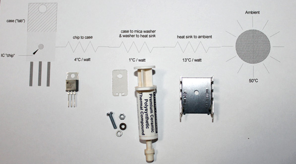
The schematic of thermal resistance along with the actual parts that make up thermal resistance.
Ohm told us a long time ago that when you have a device that has voltage across it and current running through it, it will get hot. He went so far as to say that the heat (measured in watts) would be the product of voltage and current. In better mathematical form, Ohms law for power can be expressed as P = E x I where P is power in watts, E is electromotive force in volts, and I is current in amperes.
Chip Off the Old Block
Lets take the example of our old friend the LM317 voltage regulator. The input will be a regular old aircraft battery bus that can rise to 14.4 volts when being charged. We want to regulate this voltage to 5 volts to run some digital logic, and we measure that this digital logic is drawing 750 mA of current.
What is that in the equation? Well, the voltage across the 317 is the input voltage minus the output voltage, or (14.4 – 5) or 9.4 volts. The current is 750 mA or 0.75 amps, so the power being dissipated by the device is 7.05 watts.
But that doesn’t tell us a thing about how hot the device is going to get. If the device were the size of a refrigerator, the heat would barely be detectable. This regulator, though, is about the size of a dime and the thickness of three dimes stacked on top of one another. It will get hot. How hot? There is a specification for this in the technical spec sheet. It says the thermal resistance between the little chip in the package and free (ambient) air is 50 C per watt. Thus, if the room temperature is a balmy 25 C, the little chip will be at a pretty ferocious 377 C. Thats hot enough to melt solder, so no wonder the little thing smelled hot when it was in the circuit.

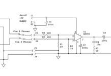
The schematic alone.
Silicon junction devices (transistors) don’t like junction temperatures over 200 C, and they get pretty squirrelly when this hot. A transistor (all of these ICs are a bunch of transistors on a single speck of silicon) running at nearly twice this temperature will fail catastrophically. I prefer to use a conservative 175 C for my design work, so lets use this figure.
What is the solution? Well, for starters we could bolt the IC to a refrigerator and get a lot of the heat out of it, but that would make installation into the airplane a bit dicey. Much better is an engineered heat sink that gets rid of the heat by radiating it into the atmosphere.
The heat sink pictured reduces the thermal resistance from the transistor case to the ambient air to about 13 C per watt, so we are getting the IC temperature down to something that we can probably live with.
Thermal resistances add in series like electrical resistances. The chip inside the case transfers heat to the metal tab on the case at a rate of 4 C per watt, so our 7-watt power will cause a heat rise at the chip of 28 C. Add a possible ambient air temperature (on the taxiway at Phoenix on a really crispy afternoon the temp can get up to 50 C), and you are already at a chip temperature of 78 C. Add the thermal resistance of the heat sink at 7 watts at 13 C per watt and you have an additional 91 C for a grand subtotal of 169 C. Thats getting real close to the limit.
Making a Connection
But there is still more. The metal tab on the IC package is generally connected electrically to some terminal of the integrated circuit, in this case to the voltage output terminal. If we are going to connect the heat sink to another metal surface, somehow we need to insulate the IC electrically from the heat sink but connect it thermally. The generally accepted way to do this is to use a super-thin mica washer between the body of the IC and the heat sink. Of course, this adds an additional thermal resistance between the IC chip and the ambient air, and we will have to take that into account. The IC is bolted onto the heat sink using a fiber shoulder-washer to insulate the nut from the metal tab.
Finally, the metal case of the IC isn’t perfectly smooth. If you look at the metal tab under a high-powered microscope, it vaguely resembles the terrain between Utah and Colorado. Lots of high hills and low valleys. Thats not good for heat conduction, because you can only transfer heat from the tops of the hills to the heat sink. The cure for that is a bit of thermal grease between the IC case and the mica washer, and another bit of thermal grease between the washer and the heat sink. This adds another 1 C per watt to the equation, so we are now up to 176 C at the IC chips transistors.
Note the words a bit of thermal grease. Too much grease is as bad as too little. You want to put the grease on so that it fills in the microinches of valleys on the metal tab and on the heat sink, but not so much that it forms a barrier to getting the maximum amount of heat from the IC tab to the heat sink. The optimum thickness is where you can still see the metal of the case through the thin film of grease.
As a last consideration, remember that this circuit will probably be inside of a closed metal chassis, and you will have to provide some method of getting the heat out of the chassis to let cooler air in. Typically, this is done with a series of small vent holes directly above and below the heat sink to make what is called chimney effect.
But now we are just a tiny bit (1 C) over the maximum temperature that we can stand. What to do? Three options:
- A bigger heat sink. A heat sink that has a rating of 12 C per watt keeps the IC chip at 169 C. Cooler than the limit, but not by much. Why not use a bigger heat sink than this? No problem if you don’t mind how big the chassis is.
- Bolting or soldering this small heat sink onto a larger metal mass. Note that this heat sink has solder tabs on the bottom. The thought is to use some PC board copper area to enhance the size of the heat sink.
- A small fan blowing ambient air onto the heat sink. This cuts the thermal resistance dramatically. How much? Thats why they make those neat laser thermometers from Harbor Freight.
Thanks for taking this little trip with me. Next month we will take a look at wire sizes and specifications, and how to interpret a wire table.


