In last month’s column I took you down the path of drafting programs that would let you document that “little improvement” you made to your aircraft. Now it’s time to think about documenting all of those gee-whiz electronics you put into your airplane.
I think it is safe to say that there are no two airplanes in the airspace today with identical electrical systems-OK, maybe a couple of brand-new airplanes just off the assembly line, a serial number apart. Cessna may have made eleventy-thousand 172s, but after a few decades of service, most of them have been modified from their factory origins (and some actually have documentation!).
So it is with homebuilts and owner-modified certified aircraft. Clyde Cessna would never in a million years claim to be the progenitor of the electrical system in my blue-on-blue ’57 182. In 1957 VOR was one of those newfangled technologies that might some day catch on. Transponder? For what? GPS? It would be October of my aircraft’s birth-year before the grapefruit-sized Sputnik would be launched. My point is that if you don’t maintain the documentation of electrical and electronics changes to your aircraft as you go, you will certainly have one huge headache on your hands when you try to do it retroactively.
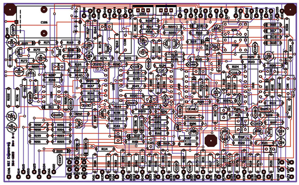
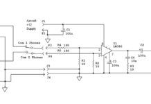
Even a fairly simple product has a relatively complex board. This one is the audio processor board of the RST-565 audio selector panel.
Picture It
The electrical diagrams that came with your plans or with your owner’s manual are somebody’s idea of what your airplane’s electrical system should look like. It is up to you to keep an accurate picture of what “nerve central” your airplane is actually carrying around.
Today’s computer drafting programs come in two major versions. There is “schematic capture,” which means that you can draw the electrical circuit diagram of your aircraft using schematic symbols (more about this later). Many of them come with what is called “pcb layout,” which lets you automatically translate your circuit diagram into a printed circuit board ready for manufacture.
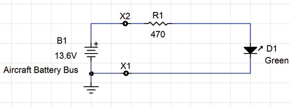
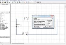
This is a screen capture of a simple circuit that lights a green LED with a current-limiting 470-ohm resistor, powered by an aircraft battery bus. Note that X1 and X2 are places in the circuit that will have wires coming into the board from the battery.
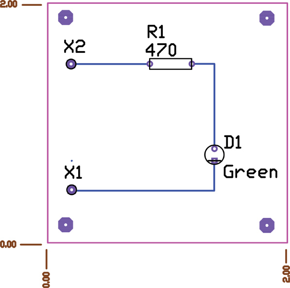
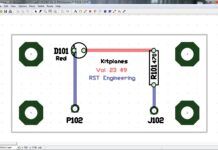
This was made from the CircuitMaker lamp schematic, and the digital file will be sent to the pc board company where it will be loaded into their pc board machine. It will be made and packaged, and the first person to touch the actual board will be the designer. The small hex circles in the corners are mounting holes for 4-40 screws, standoff, lock washer and nut. X1 and X2 are copper holes for wires to the battery, R1 is the current-limiting resistor, and D1 is the LED. You can see that the board will be 2 x 2 inches by the “shear marks.” This board probably costs 50 cents in quantities of 100.
Working with Schematics
For the time being, let’s concentrate on schematic capture. What is a schematic? Again, there are two ways of drawing circuits. One is what is called the “pictorial” method, and the other is called the “schematic” method. The pictorial actually attempts to draw a representative picture of the circuit, while the schematic uses symbols for the circuit.
For example, a 9-volt transistor radio battery is quite small, while my aircraft battery is about the size of an inkjet printer. In the pictorial method I’d have to draw these two batteries proportional in size, whereas if I were using the schematic method, they would both be represented by exactly the same size symbol. Which do you think is more efficient? I can draw an aircraft schematic diagram on a couple of sheets of paper; it would take a small book to do the same diagram pictorially. All computer drafting programs today use schematic diagrams.
OK, you’ve made the decision to document your airplane’s systems. How do you start? Fortunately, there are dozens of computer programs that make this a slam dunk. You can peruse www.everythingpcb.com/p14120.htm for something that looks appealing, or you can use three of my favorites.
Tools of the Trade
There’s the CircuitMaker/TraxMaker 2000 (or CMTM2K). This is a relatively old program developed by Art Hatfield for Microcode Engineering in the late 1990s. It is, by my standards, the best schematic capture software out there. Unfortunately, Microcode was bought out by a software giant that then proceeded to kill the CMTM2K software.
Am I biased toward CMTM2K? You bet. I was a beta tester for this software and was given license by Hatfield to distribute it “for evaluation purposes” to anybody I wished. You may download it from http://faculty.sierracollege.edu/jweir/Webpage14/com/cie14com.htm and evaluate it as you see fit. It has been out of production for about 10 years, but it is still quite usable with nearly every Windows version on the market.
The nice thing about the CircuitMaker (schematic program) is that it was written back in the day when the data files were kept in plain English, and you could make edits and modifications as you saw fit. Today’s programs use crypto techniques to keep users from being able to edit data for their own purposes.
CircuitMaker is bundled with a program called TraxMaker that lets you make a printed circuit board from your design, and also “autoroutes” it for you. That is, it shows you automatically where the tracks on the board ought to be.
As I said, I’m biased. Everything you’ve seen come out of the RST Engineering Skunk Works in the last 15 years has been a product of CMTM2K. It is a flawless piece of software.
Eagle (www.cadsoft.de) is another popular schematic/pcb layout program. There is a freeware version that does almost everything that CMTM2K does, but it has a steep learning curve, and it is limited by the number of parts you can use. There is a version you can buy that removes the parts number limitation, but it is moderately expensive.
Eagle does both schematic capture and pcb layout, but Windows users had best be prepared for some non-Windows conventions. Again, the learning curve is rather steep and is easily forgettable if you don’t use the software on a regular basis.
Designspark (www.designspark.com/pcb) is a new player on the schematic layout scene. I haven’t had more than a few hours to play (excuse me, heuristically experiment) with this software, but I am mightily impressed by what I see.
It is absolutely free, no “upgrade for more money” involved. I was impressed by the ease of creating new parts. For example, no program (including my beloved CMTM2K) makes creating new parts particularly easy, but Designspark makes it trivial.
I may be porting all of my designs over to Designspark in the next few months. Stay tuned.


