Lets go back and review just a little bit of what we learned last month about digital logic. Digital inputs and outputs have one state: high or low. High is 70% of the power supply voltage or more; low is 30% of the power supply voltage or less. A CMOS (complimentary metal oxide semiconductor) is the sweet spot among availability, speed and price. Signals between 30% and 70% of the power supply are not allowed, or they’re treated as special cases.
Lets clear up that nasty little area between 30% and 70% with a special kind of buffer called a Schmitt trigger inverting buffer (4584). With a 5-volt supply, most CMOSes are designed to switch at half the power supply, or 2.5 volts. It will be remarkably close to this for any other CMOS device other than the Schmitt trigger. This device is intended to switch low when the input gets above 2.75 volts, but not to switch back high until the input is lowered to less than 2.25 volts. This does two things, both of which are good.
One, it squares up a slow-moving analog input signal; and two, it strips off any minor noise that is on the input signal. Why is this good? In the first place, some of the circuits we will be using later wont respond to a slow signal; they require fast waveforms. In the second place, any signal coming from a sensor on the aircraft is going to be noisy. There is no way around it.
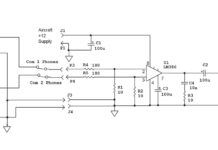
My chosen way of dealing with signals coming from aircraft switches or sensors is to do a single-stage of RC filtering (see Figure 1) and then a Schmitt inverter to square things up. I have yet to have a noise problem with any of the digital devices that Ive designed for aircraft in the last 30 years.
Behold the Gate
OK, so now we have our input coming from sensors and/or switches squared up and ready to go. Where do we go from here? The first thing well talk about are gates. No, not Bill and Melinda, but digital gates. A gate says the following: I have two or more inputs. As a logical function of the voltage at my inputs, I will give you a logic high or a logic low at my output.
Say what? OK, lets take the simplest of gates, the two-input OR gate (4071, see Figure 2). A high on either of the two inputs (or both inputs) gives me a high at the output. Use? If I have either the nav lights on or the strobe light on (or both), give me a high level at the output to turn on a panel light that says, Lights On. Or if I have either No. 1 com or No. 2 com keyed, give me a panel light that says Transmitting. Get the idea? It lets you know if either of two sensed circuits is engaged.
The normal way of showing how a digital device works is with a truth table, which simply takes all possible combinations of inputs and shows what the output is going to be for a particular device.
For example, let’s take the simple 4071 OR gate that we used above. The truth table for this gate looks like what you see at the top of the next column.
Let’s talk a bit about this turns a panel light on thing. CMOS outputs aren’t designed for high current. My rule of thumb is that I cant get more than a couple of milliamperes out of a gate or a buffer (much less from some other devices), so we are going to have to put some sort of current driver at the output if we want any sort of brightness from a lamp or if we want to run some other sort of high powered device like a relay or an earphone. Figure 3 shows the easiest way of doing this for either a high or a low at the gates output.
The second kind of gate I want to discuss is the NOR or Not OR gate (4001, Figure 4). As the name implies, the output goes low when either or both of the inputs is high. You do the same thing with a NOR gate that you do with an OR gate, but the output is simply inverted.
The truth table for the 4001 NOR gate looks like this:
Input A | Input B | Output Z |
|---|---|---|
0 | 0 | 1 |
1 | 0 | 0 |
0 | 1 | 0 |
1 | 1 | 0 |
Note that the only difference between the OR gate and the NOR gate is the output level.
Let’s take the OR gate to the next level. There will be times when you want the output to be high when either of the inputs are high, but low when neither input his high or both inputs are high. This is called an Exclusive OR (4070, Figure 5). An Exclusive OR (or XOR as it is commonly called) has some unique properties that we may want to explore in a future article.
The truth table for the 4070 Exclusive OR (XOR) gate (next column) looks very much like the OR gate, but with a little difference in the last line.
Wow, if you have stayed with me this far, you have gone through the first two weeks of my freshman electronic engineering class. Next month well start to look at some interesting digital CMOS circuits and figure out how to make some practical down-to-earth uses for these devices. Stay tuned.


