As everyone moves toward electronic instrumentation, the alternator is taking on a more and more important role. Alternators and their indispensable partners, voltage regulators, are generally pretty reliable, but they do fail from time to time. Because of this, it is important to understand how they work and what the various failures look like.
What Do the Gauges Tell You?
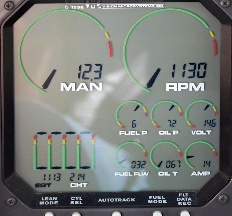
Two instruments provide important clues about your charging system—the ammeter and the voltmeter. Depending on how your plane is wired, the ammeter will tell you how much current is going in and out of your battery or how much current your alternator is producing. The voltmeter will tell you the voltage at the main electrical bus. A voltmeter is required equipment if you have electronic engine gauges—tachometer, manifold pressure, oil pressure, etc. These two gauges tell you quite a bit about the state of your alternator in particular and your electrical system in general.
Normal readings should be around 14 volts for a so-called 12-volt system. This is because the voltage output of the alternator must greater than the battery voltage or current will not flow into the battery, which on its own should produce about 12.8 volts when fully charged. If you normally see system voltage that is above 14.5 or below 13.8 when flying, you need to find out why. Too little voltage will not charge the battery properly and too much voltage can damage it permanently. When the alternator fails, system voltage will drop to battery voltage, which will be at 12.8 or less, and declining as the battery loses charge. At somewhere around 9 to 11 volts, your electronic instruments and radios will cease to function. This will vary from one device to another and is a number that you should know for your equipment, especially if you fly IFR. In the case of radios, transmitting will fail before receiving because just keying the mic will cause system voltage to drop a bit. This is why a voltmeter is required with electronic engine monitoring systems. The best insurance against a total alternator failure is a backup power source, which is now standard or at least an option with most electronic displays.
A slight increase in voltage may indicate resistance building up in the field circuit for some reason. A corroding connection or a partially broken wire could be the cause. The failure of one of the stator coils could also cause voltage to rise. The important point is that just as decreasing voltage is bad, so too is increasing voltage. If it changes, there must be a reason.
Normal ammeter readings will vary depending on what you have installed and turned on, and depending on how you have wired your ammeter. It is very wise to have a good idea of how much current each device draws in case you need to shed load in a hurry to preserve your battery. When flying sometime, try turning off each device in your plane and see how the current changes. Then make a note of it in case of an emergency. Pitot heat, incandescent lighting and landing-gear and flap motors are typically the big power hogs in most airplanes.
Alternator Failures
Failed alternators cause relatively few electrical failures. The various alternators likely to be used in Experimental/Amateur-Built aircraft should last for 2000 hours, the TBO of a typical aircraft engine, and will require no service during that time unless abused or improperly installed. Of course, relatively few is not the same as none, but look elsewhere first unless the alternator displays obvious signs of distress.
Wires and connectors are the most likely culprits when things stop working. Just as with starter problems, track down each wire, switch and connector to see where resistance is high—above 0.2 ohms across any switch or connector—and/or where voltage drop is excessive—more than 0.5 volts. Get a good multimeter that will reliably measure tenths of ohms and learn how to use it.
There are some mechanical problems that could also case your alternator to underperform or fail. If you hear a high-pitched squealing sound when you place a heavy load on the alternator, you may just have a loose belt. Lycoming has a service instruction that tells you how to properly tighten your alternator belt. Keeping your alternator belt properly tightened helps ensure a long life for the belt. Since replacing a belt means taking off the propeller, getting a long life out of it is really important.
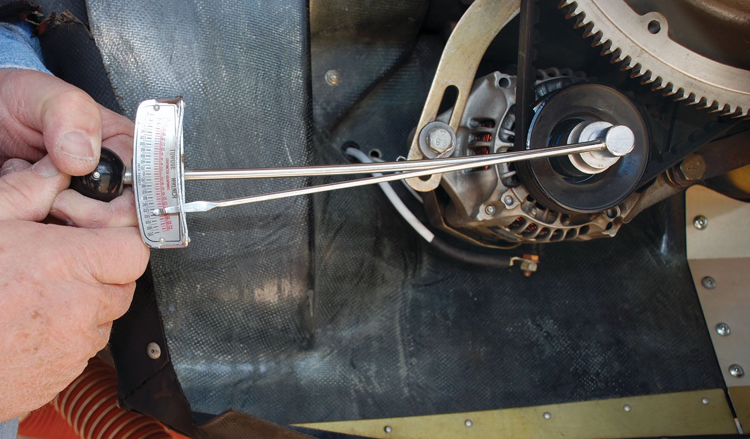
Alternator Belt Tension
 Use a torque wrench on the pulley belt and adjust the tension so that you get the specified torque just as it starts to slip. Turn the pulley nut in the tightening direction so you don’t risk loosening it. Reference: Lycoming Service Instruction 1129D.
Troubleshooting
With any kind of troubleshooting, there are a couple of rules of thumb that are worth considering. One, start with the simple stuff, then move to the complex items. And, two, which is similar, start with the cheap stuff first, then move to the more expensive things. For example, if the alternator is not putting out any power, check the field wire before ordering a new alternator. It is just easier to fix simple things, even if it is not always easier to find simple problems. And if, in desperation, you devolve from mechanic to parts changer, you sure as heck want to start changing the less expensive things first. These are not hard-and-fast rules, but really more like guidelines. Sometimes the problem is obvious and it is obviously expensive, but when you are having a hard time figuring things out, these rules can help you keep things in perspective.
Common Alternator Problems
If you have a mechanical whining that increases pitch with increased rpm you may have a bad bearing in your alternator. If so, sending it back to the manufacturer or a repair shop for overhaul is probably your best bet. Mechanical noise is different than radio noise, so turn your radio off if you aren’t sure of the origin of the noise.
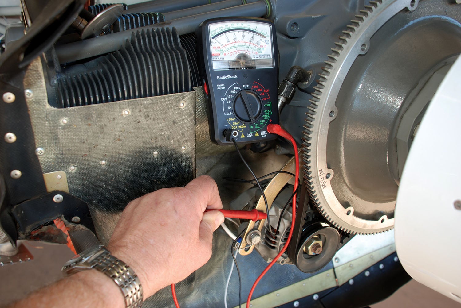
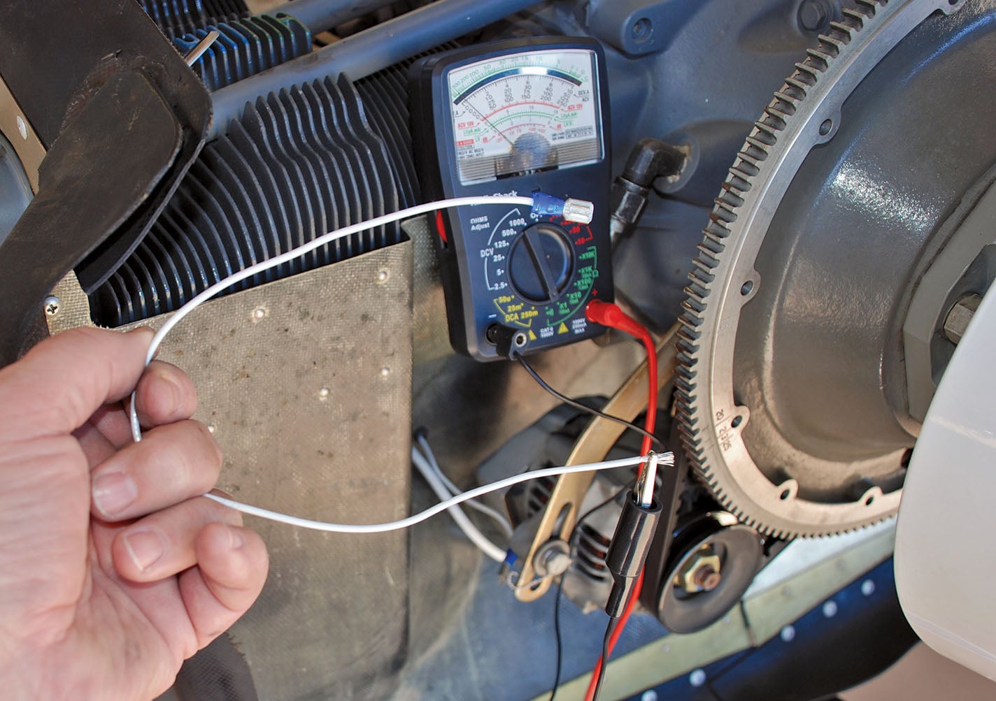
If the alternator just stops charging, the first thing to suspect—assuming it isn’t making some terrible noise or hasn’t blown the main breaker—is the field. If you are not getting 12 volts or more to the field terminal of the alternator, you are not going to be making electrical power. Check the connector at the alternator, the wire, the voltage regulator (if you have an external voltage regulator) and then the ALT side of the master switch. If you don’t have 12 volts at all of these points when the master switch is turned on, find out why and fix it. Loose connectors can be the toughest problems to find, so be sure to tug on each one to make sure it is secure. If the field breaker has popped, suspect a chafed wire making contact with the airframe somewhere. Trace the entire path of the field wire until you find the short.
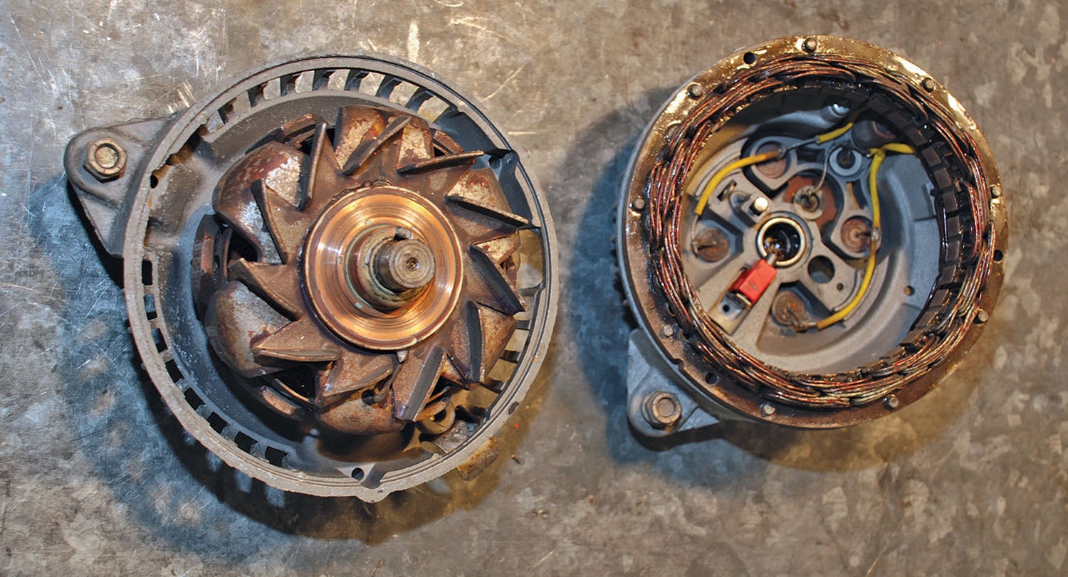
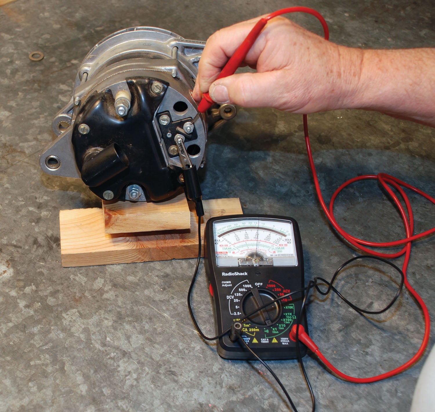
A short from the field to the alternator case inside the alternator can also cause the field breaker to trip. Disconnect the wire from the field post of the alternator and use your ohmmeter to check for a short by placing one lead on the field terminal and the other on the alternator case. If there is no or almost no resistance, you have a short inside the alternator. You should expect to see at least 4 to 6 ohms between the field terminal and ground, assuming a 12-volt system. In some cases, the field is not internally grounded. You can tell this by the existence of two field terminals on the alternator (usually marked F1 and F2). In this case, measure resistance between F1 and F2.
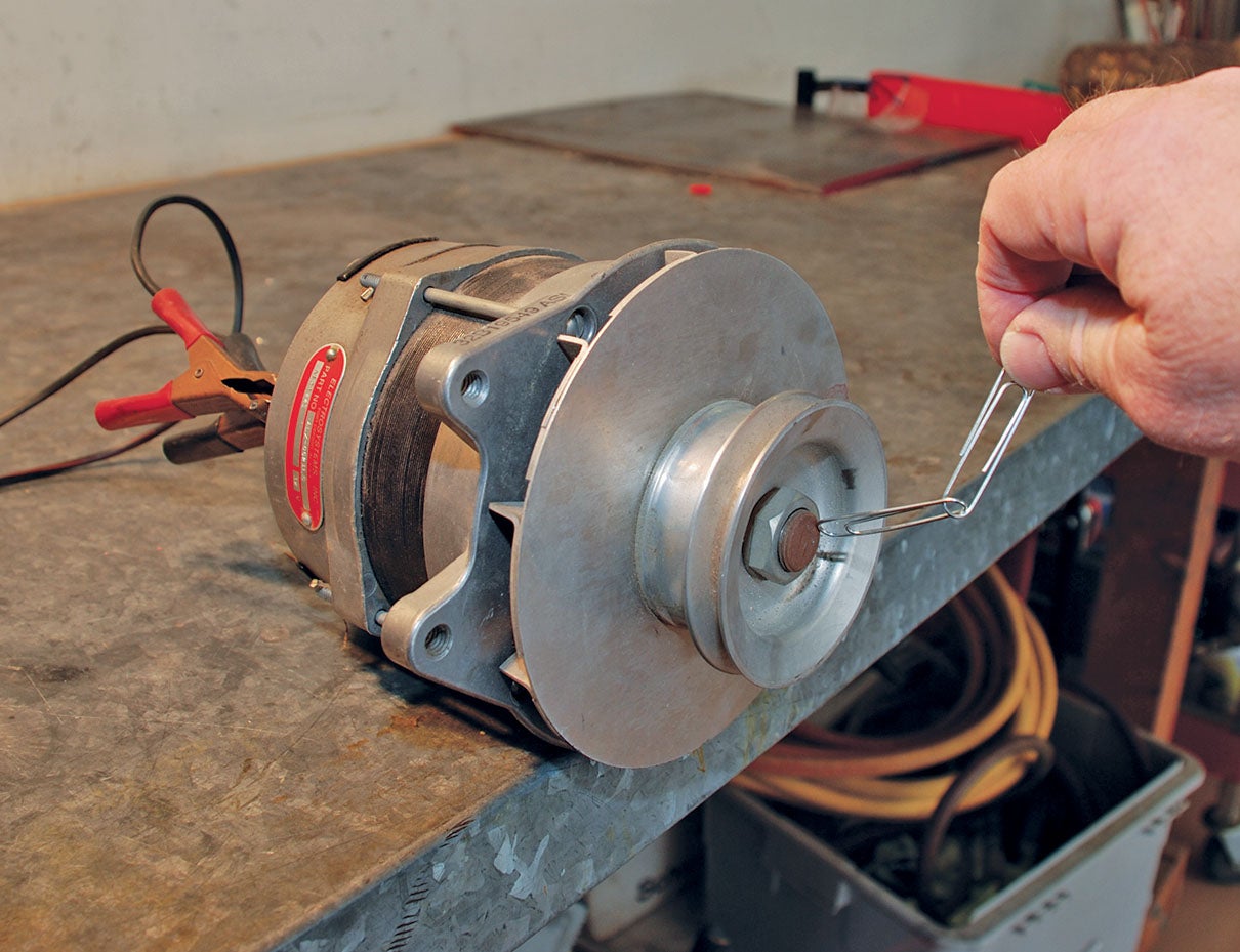
In other cases, you may have a poor connection between the brushes and the slip rings inside the alternator. To track this down, disconnect the field wire and the alternator belt. Then turn the alternator over by hand while checking resistance between the field post and the alternator case (or F1 and F2 if that’s your configuration). If resistance is consistently high, the contact between the slip ring and the brushes inside the alternator is not good, which means the alternator needs to be repaired. You may be able to cure this problem by using a fine Scotch-Brite pad on the slip rings. If you have an open circuit across the field (infinite resistance), you may have brushes that have fallen apart or a broken wire in the field winding. Time for some major alternator repairs.
Because of their extremely low operating current, digital multimeters do not do a good job of measuring resistance in the field circuit, so it is best to use an old-style analog meter for this. Even if you get a reading of 50 ohms or so there is no reason to panic. Spin the alternator a few times and see if the resistance goes down. You may also notice that the reading varies as you spin the alternator. This is pretty common and not necessarily a reason for concern if the alternator is otherwise working well. A thin layer of oxidation on the slip rings can easily produce some extra resistance. Higher resistance indicates a possible problem worth further investigation.
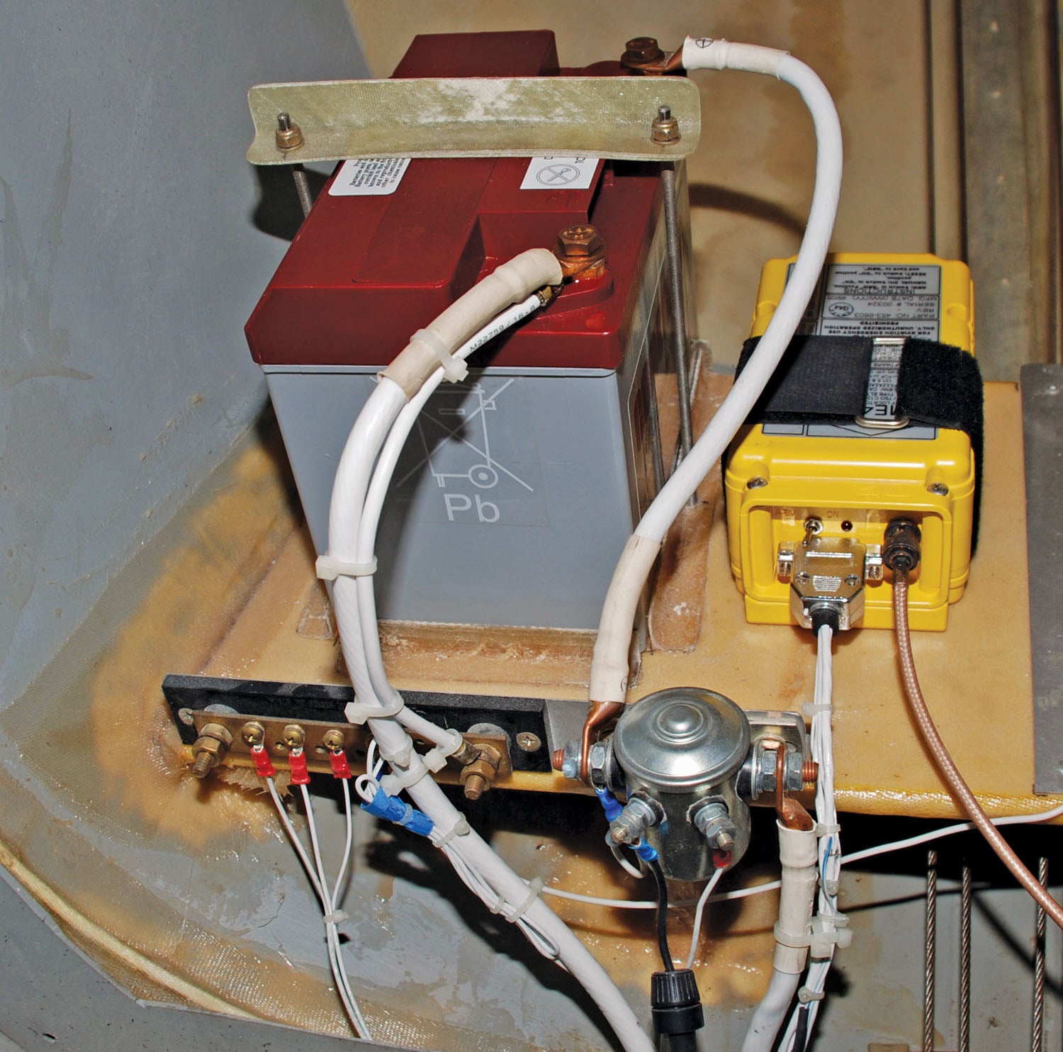
If the field wire and the alternator wire short against each other, you will get a potentially very damaging overvoltage situation. A partial stator failure can also cause the field to trip if it has caused an overvoltage spike. Make sure all wires are properly routed and secured so that they can’t rub against each other. The price of this mistake can easily run into the thousands of dollars. To guard against this, make sure your alternator has built-in overvoltage protection or use a voltage regulator that does. Rapid loading or unloading of the alternator can also cause overvoltage surges. Some of the current models of Plane Power alternators have internal overvoltage protection, but others do not. Be sure to find out if this is included in your alternator. This is especially critical if you are using a lithium battery such as the EarthX. These batteries have their own overvoltage protection, but a runaway alternator can overwhelm that protection in extreme cases, possibly leading to disastrous results. (By the way, do not fail to install the battery warning light that comes standard with an EarthX battery if you have one in your plane.)
B&C alternators as a rule do not have built-in overvoltage protection, instead relying on the overvoltage protection built into the B&C voltage regulator. At first this seems like an unnecessary addition of cost and complexity, but the B&C setup has proven to be very robust in the field, making the extra complexity worth the cost.
If you have an overvoltage situation and you have overvoltage protection, it should trip the field circuit breaker. In such a case you will need to turn the power to the field off (ALT side of master switch) to reset the overvoltage module. Of course, the next thing to do is find out why you had a voltage spike so it won’t happen again.
Rotax Alternators
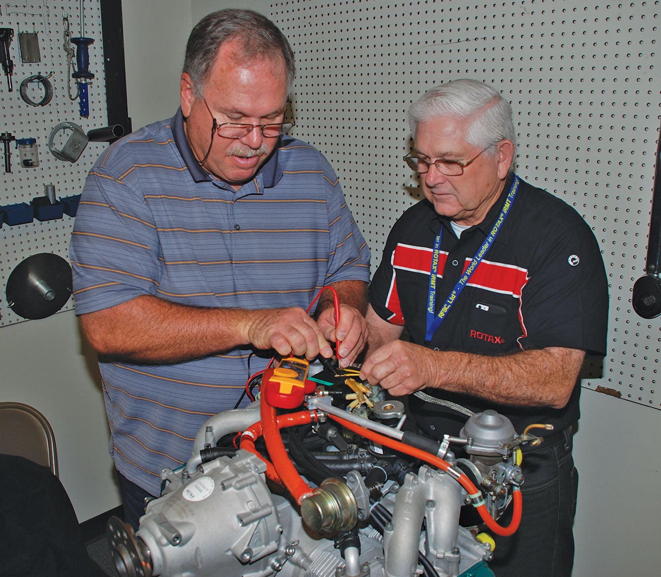
The Rotax charging system is a special case and calls for its own diagnostic and repair procedures. There are some simple resistance checks that you can perform to check the alternator. First, disconnect the alternator at the plug. Check resistance between the yellow wires and between each yellow wire and ground. Yellow to yellow should measure 0.1 to 0.8 ohms. Yellow to ground should be open (infinite resistance). Next check the resistance between the red wire and ground. This should be in the range of 3.2 to 4.5 ohms. The two-colored wires are for the ignition system.

If the unit does not pass these basic checks, it most likely needs to be removed and further checked and/or repaired. For more detail on these procedures, refer to the Maintenance Manual (Heavy Maintenance) for Rotax Engines Types 912 and 914 Series, which is available online. Troubleshooting is also covered in the Rotax maintenance training courses, which are highly recommended to anyone who works on Rotax engines and are required for S-LSA Rotax mechanics. (In case you missed it, Vic Syracuse attended the Lockwood Rotax school and wrote about it in our May 2020 issue.) The nice thing about the Rotax troubleshooting procedures is that they are very straightforward and can be performed with a good multimeter.
Rotax engines have built-in alternators that do not include overvoltage protection. According to California Power Systems, the west coast Rotax distributor, Rotax considers it acceptable to use a lithium battery in their engine installations if the battery has overvoltage protection built in. The EarthX batteries include such protection. However, a more robust installation would include external protection in addition to that included in the battery. For a more detailed description of the Rotax charging system, look for the webinar in the EAA archives about the Rotax 915 electrical system.
Radio Noise
If you are getting radio noise that seems to be alternator-related, you can use your multimeter to do a quick check of the alternator output voltage. Set your meter to AC voltage and measure from the main bus to ground while the engine is running. If you see more than one volt in the AC scale, suspect a blown diode inside the alternator or possibly bad brushes. Remember, the alternator is only supposed to output DC voltage. This isn’t a perfect test but it is quick and easy. A ripple meter is an even better way to check stator and diode condition, but most builders will not have one in their toolbox.
Suddenly occurring and persistent radio noise is probably caused by a bad diode or a broken stator wire in the alternator. This means a trip to the alternator shop. Intermittent noise is more likely caused by a ground loop, which in turn is likely caused by a bad connection to ground somewhere. Electrical systems that employ a central ground bus are seldom plagued by ground loop problems, but using the airframe for a ground leaves you more vulnerable. These problems can be tough to track down, but simply making sure every single ground connection in your plane is secure and corrosion-free is where you need to start.
Getting to the bottom of alternator and charging-system troubles is a matter of understanding the systems and taking your time to thoughtfully troubleshoot in a logical fashion. Do that and your alternator will come back “on line” to serve another day.
Photos: Dave Prizio and courtesy of B&C Specialty Products, Inc.
![[Credit: Lisa Turner]](https://www.kitplanes.com/wp-content/uploads/2026/02/Fuel-Selector.jpg?w=218&h=150&crop=1 "Fuel Follies")


I have a px 5000 voltage regulator 12 volt which they do not make anymore what do you suggest I can replace this with in order for my bus to start to work have a rebuilt alternator but the regulator is not producing anything to keep the alternator and the battery going
Comments are closed.