Over the past few months, we’ve discussed a lot about antennas, what to make them out of, how long they should be, and other important design factors. Now we come to where the copper meets the ionosphere.
All we’ve been able to say so far is that we can tell how much of the transmitter power (or receiver signal) is absorbed by the antenna and how much has been reflected back to the power source.
Now comes the real test—how much of that power is really being transmitted or received, and in what direction. Perhaps it is now time to introduce a concept that is practically impossible, but is a nice theory to measure our antenna against. We call this concept an “isotropic radiator.” An isotropic radiator transmits or receives from all directions equally well—and is impossible to make. Think of a transmitter sitting in the middle of a copper basketball; the “pattern” of the radiation of that basketball is equal in all directions: left, right, forward, back, up, and down. It is a truly spherical pattern. Practical antennas can’t do that.
The Truth
And here I will make a claim that may save you a few bucks in buying antennas: Antennas cannot make power. If somebody tells you they have an antenna that increases your transmit or receive range “all around,” then run—do not walk away. Antennas pretty much work like a nozzle on the end of your hose. There is only so much water pressure and volume that you can have. You can have a round sprinkler that distributes that water over a relatively large area with each point of the water compass getting an equal amount, or you can have a nozzle that squirts that water in one direction at the expense of all other directions.
In the amateur radio “ham” world, we call antennas that squirt power at one point “beam” antennas, just like the beam of a flashlight. All the power (light) goes in the direction of where we point the antenna (flashlight). TV and FM radio stations have a far different problem, but approach it in the same way. Here the broadcast stations want to have their signals heard a maximum distance, but don’t care about transmitting up or down. We have design ways of taking that signal and squishing it top and bottom, so that the radiation pattern looks a lot like an LP vinyl record (remember those?). Here, all of the signal is being squirted at the horizon and very little goes up or down. Working a satellite takes both of these techniques and forms a pencil beam that is pointed at one precise spot in the sky.
The problem, of course, is that the techniques for doing this make the antennas very large compared to, say, the Romex Ranger ground plane we designed a few months ago. You could probably fit the Ranger (or a variant) onto your airframe, but hoisting an FM broadcast antenna onto your plane might possibly be done if you are building a C-5 Galaxy.
What We Can Do
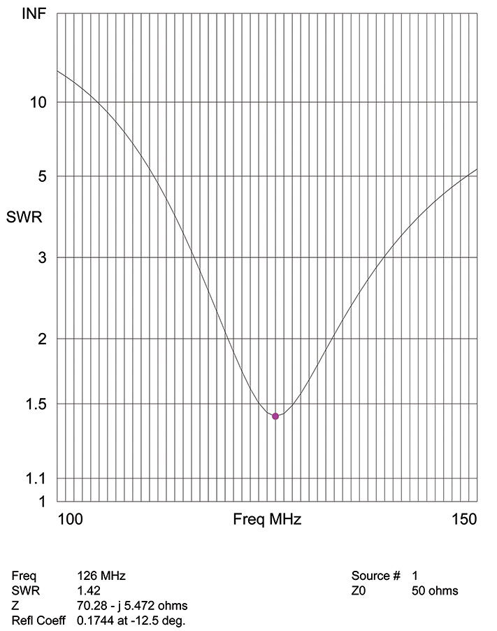
What does that leave us? Simple dipole “rabbit ears” and whip “spike” antennas. So, what does the radiation pattern of a dipole look like and where might we use it? Considering that aviation band nav signals have their signals horizontally polarized (they vibrate horizontally with respect to the earth’s surface), we need a set of rabbit ears whose ears are laid out horizontally. Such an antenna, with elements roughly a quarter of a wavelength long, is the best we are going to be able to do. I’m sure by now you are tired of seeing the old VSWR curve showing the “goodness” of this dipole over frequency (Figure 1). What you have not seen to date is what the antenna looks like schematically as a plain old dipole (Figure 2).

Figure 2. In this dipole antenna schematic, the aircraft’s nose is on the Y axis, and the wingtips are on the X axis.
At this time, let’s take a further look at the antenna schematic drawing. The airplane is represented by those little circles in the center of the antenna. The X axis is what we call the lateral axis of an aircraft, the Y axis is the longitudinal axis, and the Z axis is the vertical axis. If you want to relate it to an aircraft in flight, the aircraft is flying to Y with the wings pointing on X and climbing or descending on the Z.
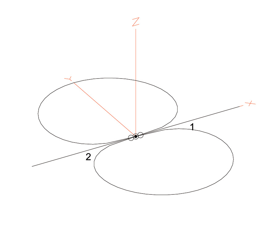
Figure 3. A three-view representation of how there is very little antenna response directly off of the wingtips with the dipole antenna.
How does this antenna radiate? In some directions, excellent. In others, not so much. In Figure 3, the airplane is in the center of those dotted circles and the nose is along the Y axis. The antenna response is shown by the black circles; and we can see that, fore and aft, it is a pretty good antenna, but a station off the wingtips has almost zero reception.
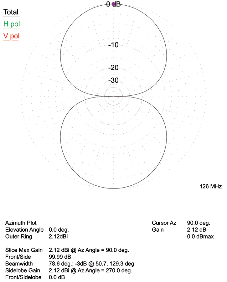
Figure 4. This antenna response plot shows that there is almost zero reception off of the wingtips (to the right and left of the figure). The data block at the bottom shows the gain or loss (in dBi) relative to an isotropic antenna.
Just to prove a point I made earlier, look at the radiation pattern from the top (Figure 4). The data line at the bottom “outer ring” shows the antenna gain or loss in dBi (decibels relative to an isotropic source)—a way of measuring power gain and loss.
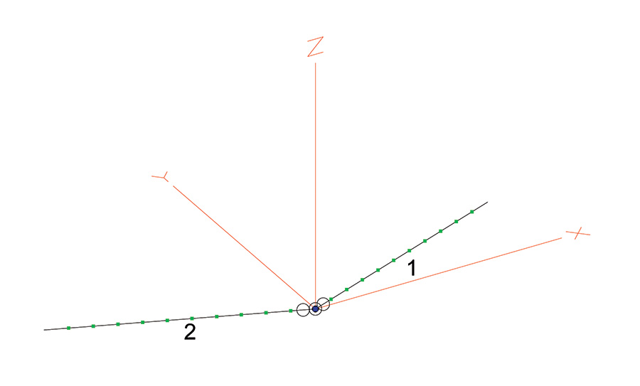
Figure 5. If we angle the dipole antenna elements slightly, we can fill in some of the coverage off of the wingtips.
Putting a slight angle onto the dipole elements (Figure 5) fills in the null off the wingtips with a slight reduction in the fore/aft gain, but allows reduced reception (Figure 6) to the sides of the aircraft (Figure 7). Experimentation shows that an angle between each of the elements and the X axis of 20° to 40° is a good compromise for dipole antennas. You will also find that the dipole with the V angle has slightly better reception in the apex of the V, and is generally pointed forward.

Figure 6. Angling the antenna slightly provides some coverage off the wingtips—at the expense of strength off the nose and tail.

Figure 7. The effects of angling the elements is apparent in this three-dimensional plot—increased lateral coverage at the expense of fore/aft signal strength.
Real Antennas—Real World
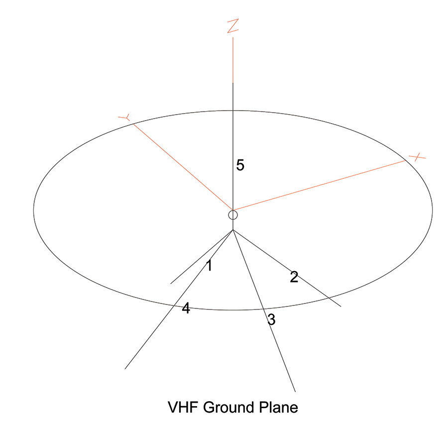
So what is the pattern for our good old vertically polarized Romex Ranger (and by extension, whip antennas on metal aircraft)? The schematic (Figure 8) shows the radiation pattern in a horizontal direction to be nearly perfectly circular, but the horizontal pattern shows huge nulls top and bottom. But this is OK, especially for a ground station. Rarely do you want to talk to a station directly over you (and I do mean directly!). One or two degrees the other side of direct will be just fine. Same for ground stations; rarely are you directly over the Unicom or tower when communicating.
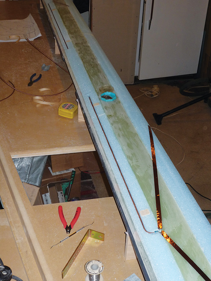
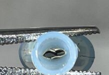
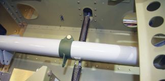
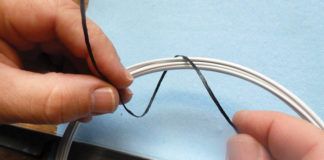
What do these antennas look like as a practical matter? You have pictures of the Ranger from last month’s issue, and below is a horizontal dipole antenna being installed into the wing of a plastic airplane; this is the connection of the coax cable to the antenna elements.
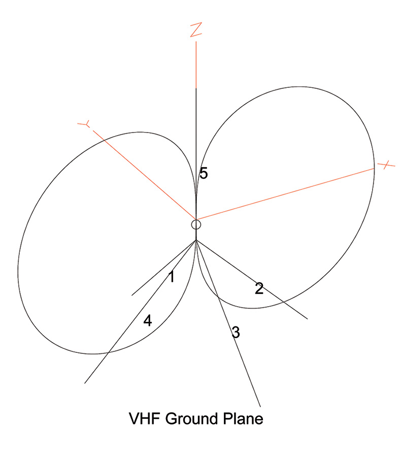
In the vertical plane, we can see that the Romex Ranger is virtually blind when looking straight up.
I’ve still got that problem from the boss I mentioned last month with whip antennas getting into the radios and instruments, and making the instrument panel into a Christmas tree; I’ll attack that one as soon as I can find one of those old ceramic base, very thin antennas. Stay tuned.

![]()
Jim Weir s the chief avioniker at RST Engineering. He answers avionics questions in the Internet newsgroup rec.aviation.homebuilt. His new wife Cyndi was his high school sweetheart 50 years ago and now she keeps Jim from making stupid blunders in spelling and grammar. Check out www.rst-engr.com/kitplanes for previous articles and supplements.

