
As promised, Lycoming delivered the Thunderbolt engine in December to Vertical Aviation. Since this was the first Thunderbolt engine to be installed in a Hummingbird, it was important for Brad Clark at Vertical Aviation to make sure it was going to fit in the engine mount. There were some minor differences in the cold air induction from the previously installed Titan engines and, sure enough, one of the cross tubes on the engine mount needed to be modified to provide some necessary clearance. That meant I had to remove my already-installed engine mount, which gave me some pause.
The engine was delivered to Vertical Aviation right before Christmas, and Brad had it and the new mount ready the week after Christmas. Carol and I drove down to pick it up. It was kind of ironic to be stuck in horrendous holiday traffic with our aircraft engine in the back of the truck.
It sure looked gorgeous when we got it home, but all I could do was look at it, as I was scheduled for gallbladder surgery the following week. I staged it as best I could, as I knew I would have weight limits for a while after the surgery, and I had to get the new engine mount installed first.
I had jumped ahead while waiting on the engine and had already installed the original engine mount. Once the mount was installed, I had installed the fuel bladder into the fuel cell area. Unfortunately, the lower bolts of the engine mount are installed headfirst from inside the fuel cell. I was not looking forward to removing all of that. I had put many layers of tape over those bolts to keep them from rubbing against the fuel bladder, and Brad mentioned that the tape should hold them in place. Removing the mount was no issue. I was hoping I could install the modified mount back over the bolts without pushing them back into the fuel cell. I thought about filling the tank with fuel to help keep pressure on the bolts but decided against that. Sure enough, I lucked out and the mount slid over the bolts enough that I was able to grab them with long-nose pliers and pull them completely through the mount holes. Yeah!
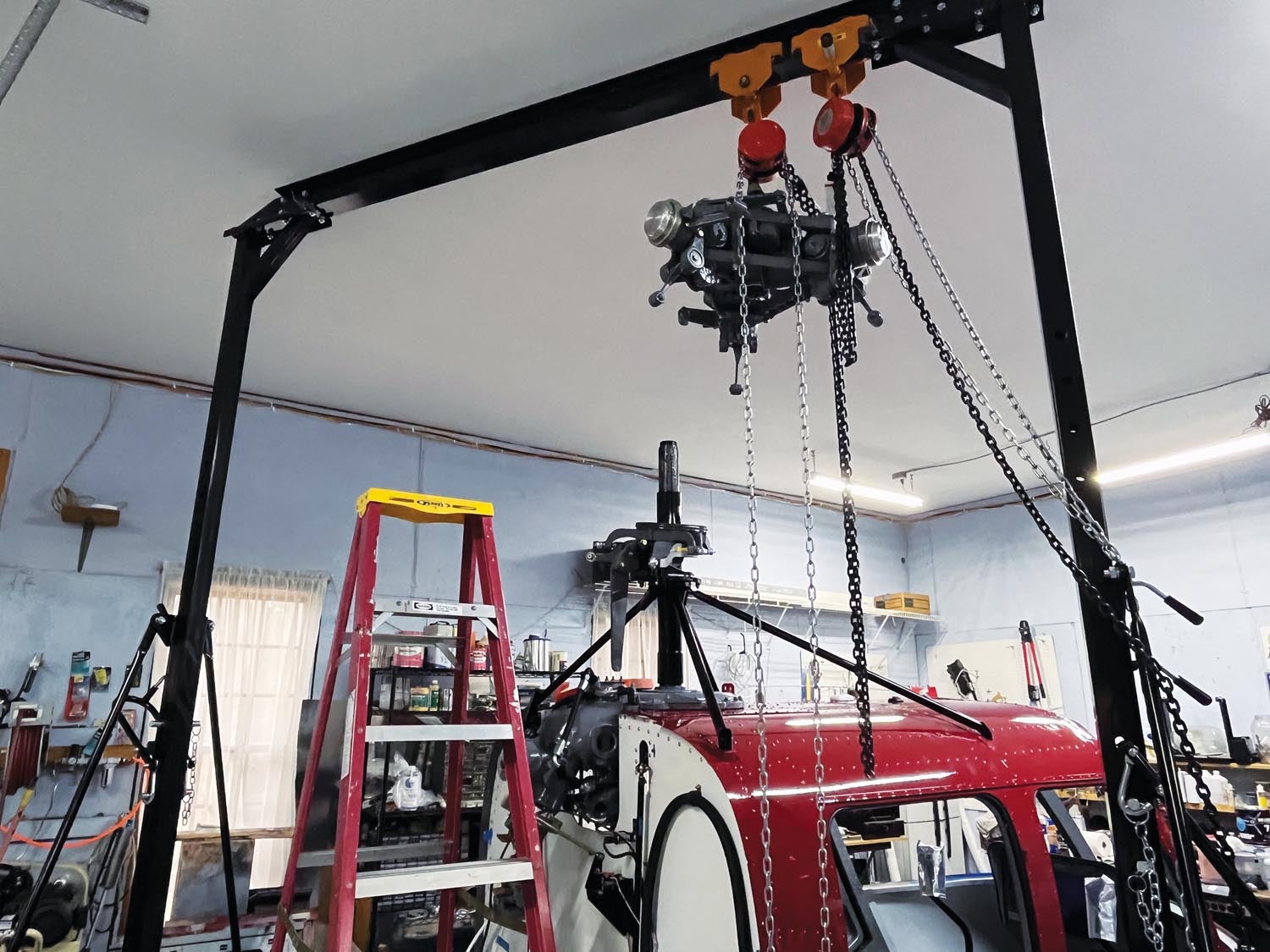
I had a day left before surgery, so I managed to get the pylon and rotor head installed. The gantry crane made small work of that. It also gave me an idea: If I staged the engine on the crane prior to surgery, I could still get it installed soon after the surgery. So that’s what I did.
Getting Back To Work
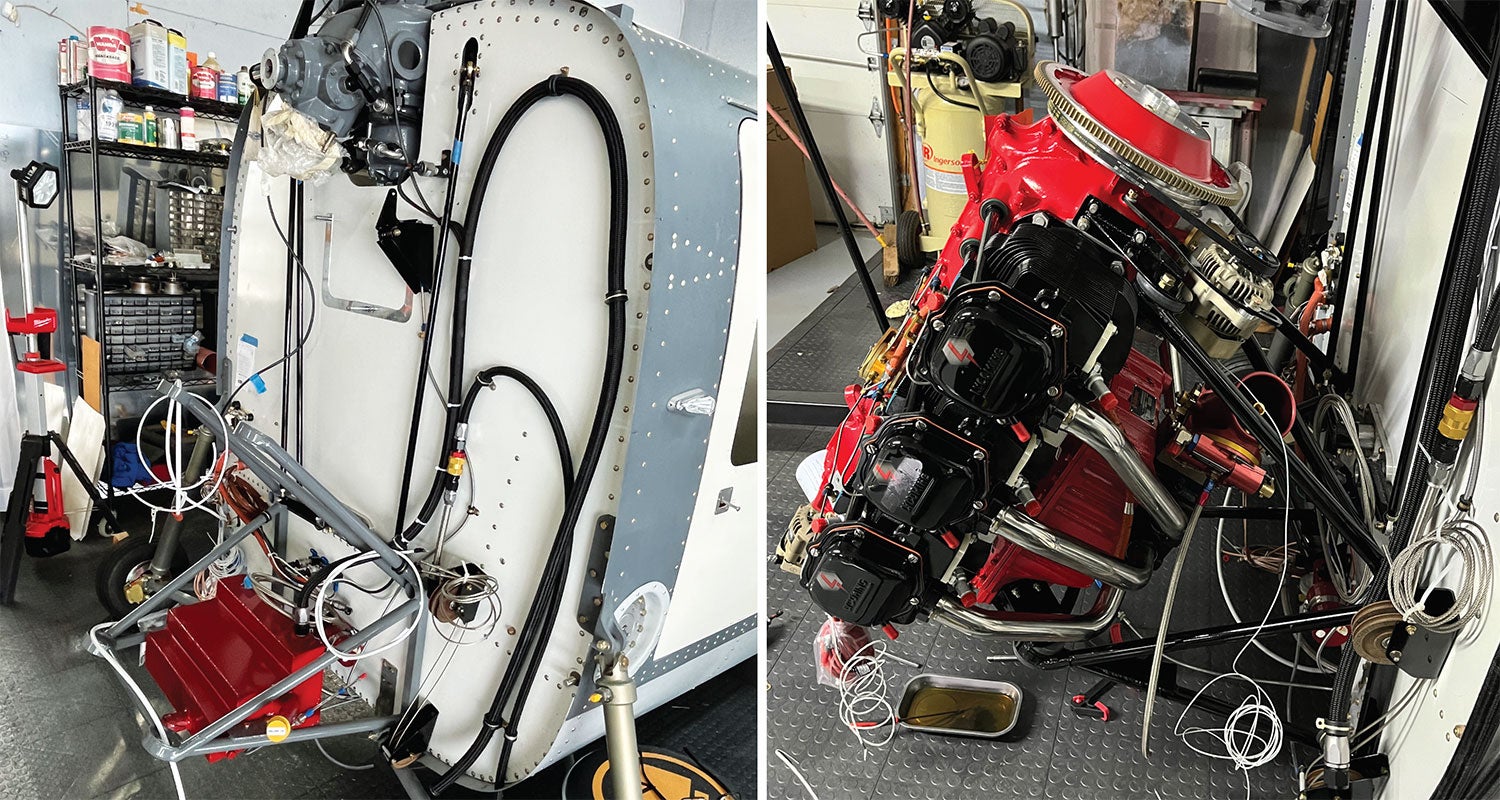
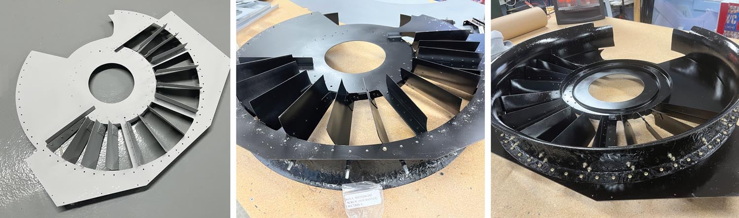
The gallbladder surgery only kept me down for a day, so I managed to let the crane do all the work and got the engine installed rather quickly. The engine rests on the Lord mounts at a 60° angle, making it much easier to install than on an aircraft using a Dynafocal mount. It sure looked pretty, but it was time to get busy, as a helicopter installation is a lot more complicated than an aircraft installation. Most of the ancillary items such as starter, alternator, fuel system and ignition systems are the same, but I needed to build and install the fan shroud and intake baffling, along with exhaust and mufflers, and make some more engine modifications. The engine is air-cooled and needs a source of cooling air since there is no propeller spinning all the time as in an aircraft installation.
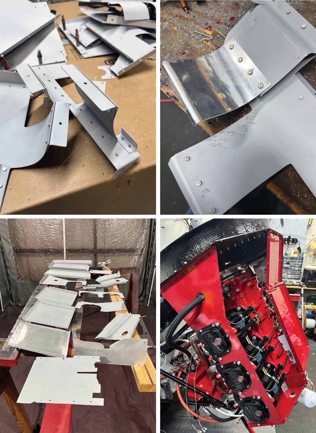
Most helicopters have some sort of fan that produces cooling air anytime the engine is running. I riveted the fan shroud together on the workbench, then installed it on the engine along with the rubber baffling. This work was becoming harder now, as I found myself standing on ladders and step stools for many hours each day just to be able to reach everything.
Due to the 60° mounting angle of the engine, some modifications needed to be made to the oil system. The oil system is a dry sump, with a separate oil tank mounted underneath the engine. The cylinder rocker covers have oil drain tubes that are connected to a drain rail that also connects to the remote sump instead of the engine crankcase as in a horizontal installation. This setup also required a modification to the oil sump screen outlet. Normally, the oil in the engine sump is picked up by the oil pump and distributed throughout the engine. In this case, a different fitting had to be installed at the oil inlet screen to allow the pump to suck oil from the external sump. Luckily, Lycoming has this part. By the way, the internal inlet to the sump screen inside the engine had to be blocked, which had already been done at the factory.
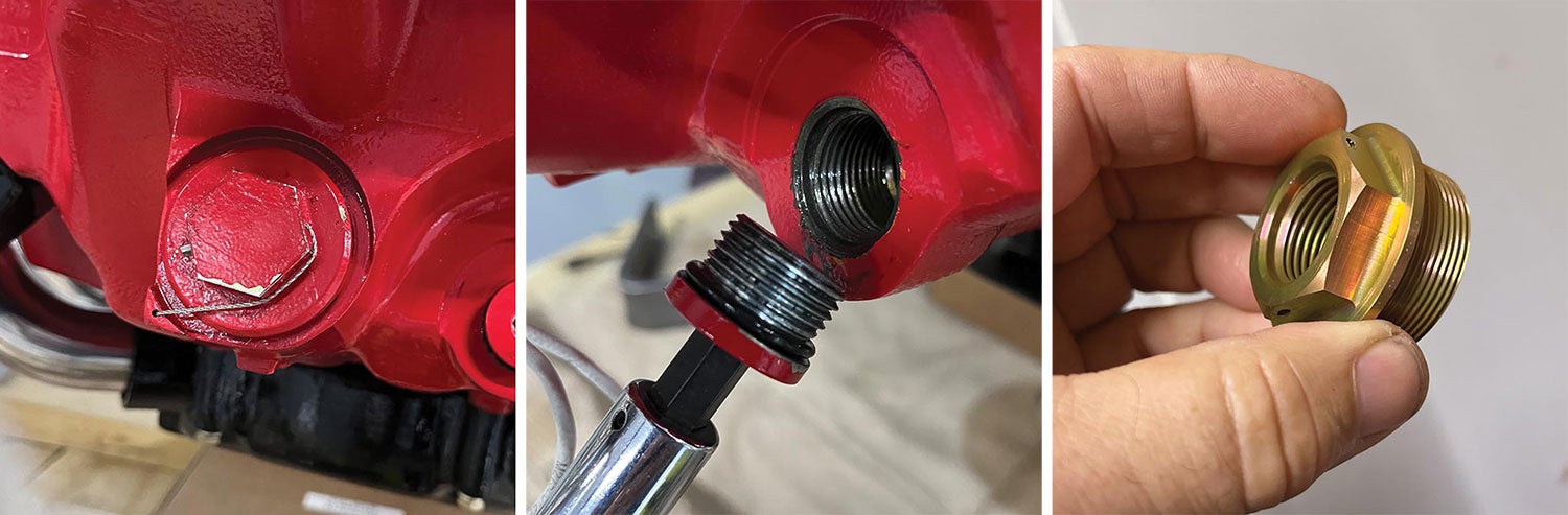
I realized I had to make one other modification. Injected engines usually have a sniffle valve located in the sump. The purpose is to allow drainage of fuel from the sump, which usually occurs after shutdown due to drainage from the injector lines into the cylinders. Normally, the sniffle valve is located on the bottom of the sump and there are two tapped bosses in the sump to accommodate the valve. Since this engine was not mounted horizontally, those bosses would not work. I very carefully drilled and tapped a hole in the rear end of the sump to allow proper drainage. I mentioned it to Chris Gayman, director of the Thunderbolt line at Lycoming, and he was fine with it.

Always More To Do
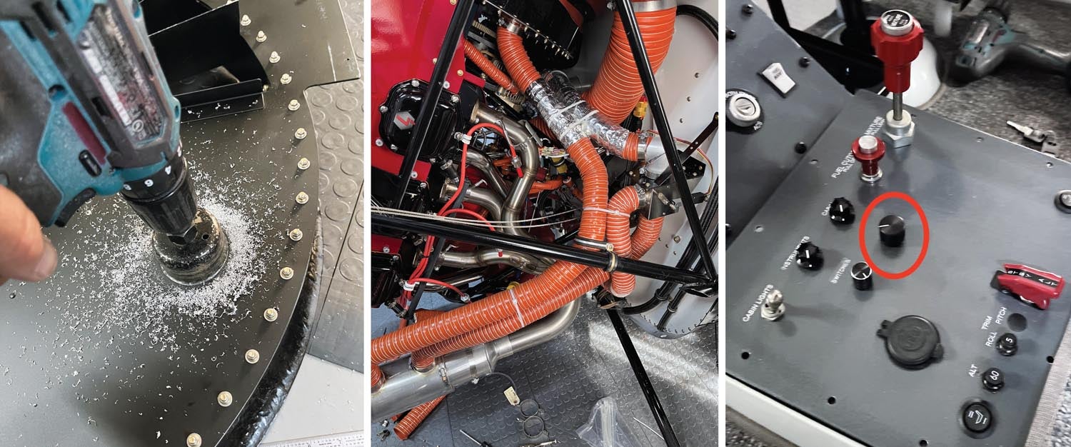
As I was building the fan shroud, I realized there weren’t any provisions for cabin heat. I had installed electric seat heaters in the front seats, but a warm cabin sure would add to the comfort factor. After speaking with Brad Clark about it, we decided it was OK to tap off the bottom of the fan shroud for some forced air. I spoke to Clint Busenitz at Vetterman Exhaust and he agreed to figure out a muff system for the muffler. A month later I had a working cabin heat system, using a TCW remote servo to control the heat box.
Vertical Aviation now supplies some nice premade baffling for the engine, which until recently had a canvas covering over the cylinders. Amazingly it still took about a week to get it all fitted, painted and installed. One of the things I noticed is that the lower cylinder baffling wraps on the Number 1 and Number 6 cylinders were missing. I riveted on some pieces so I could tie them together across the bottom and mentioned it to Brad. Sure enough, somehow, he had forgotten about them on his, and he had noticed that the Number 6 cylinder was running hotter. For proper cylinder cooling, it is important that the air circulates around the cylinder prior to exiting out the bottom. If you have too large of a gap, or no wraparound at all, the cylinder will run hot. One of the first places I look is at the underside of the cylinders when a customer mentions that the engine is running hotter than usual. Often the linkage between the front and rear lower cylinder baffles has come loose or broken.
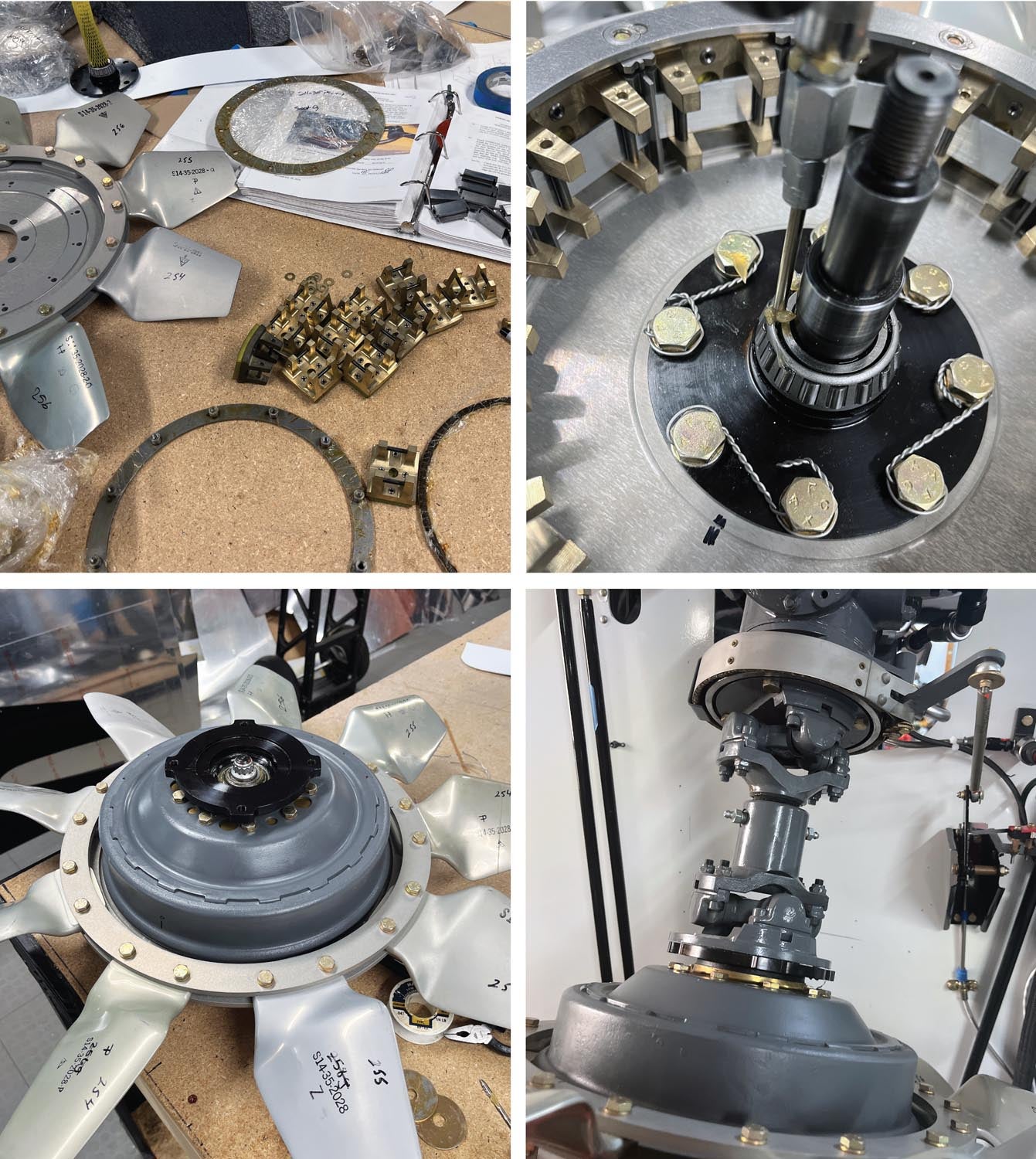
Now it was time to fabricate all the hoses for the fuel, oil and sensors. That was no small task, and I also took the time to add heat shields to quite a few of them. At this time, I also managed to get the clutch assembly built up and installed, along with the coupling between the engine and the transmission. The clutch assembly is quite a project, but also rather simple in its operation. Basically, it is a centrifugal clutch and sprag clutch combination. Once the engine is running above fifteen hundred rpm, 12 shoes are forced out against the inside of the drum, which then starts spinning. The sprag clutch engages the transmission, which turns the rotors. In the event of an engine failure, the sprag clutch allows the rotor system to freewheel from the engine. The whole clutch/fan assembly is quite heavy and probably pushed my after-surgery weight limitation requirements, but it all worked out.
I had to make one more layer of baffling for the engine compartment. The purpose of this layer is to prevent the engine fan from sucking all the hot air from beneath the engine, which is especially important during hover operations when the engine is running at higher power settings than in cruise flight.
Getting Close To Finishing
Next came an exciting activity—attaching the tail cone. In Part 4, I mentioned that the paint on the tail cone had not come out as perfectly as we would have liked. The annoying thing was that it was in our faces every day as we walked out to the hangar. Finally, one day I sanded it all down and repainted it (see Part 5). It’s much better now!
With the tail cone attached, there were some big items left. I had buggered up one of the cowlings when I had previously installed the cowlings, and we had picked up a replacement at Vertical Aviation when we picked up the engine. So, I had to redo it and hopefully not make the same mistakes. I’m not patient when it comes to rework, but I took my time, and it came out much better than the first one. I also had to redo the windshields, as I cracked the left one when installing it the first time. The advantage was that we ordered tinted replacement windshields, as that glass bubble can make for a hot cabin environment during the summer months. The disadvantage is that the windshields and nose are certificated parts from a Jet Ranger helicopter. That means they come with a certified price tag. Using a Dremel with a diamond cutting wheel on the windshield made cutting the plexiglass much easier.
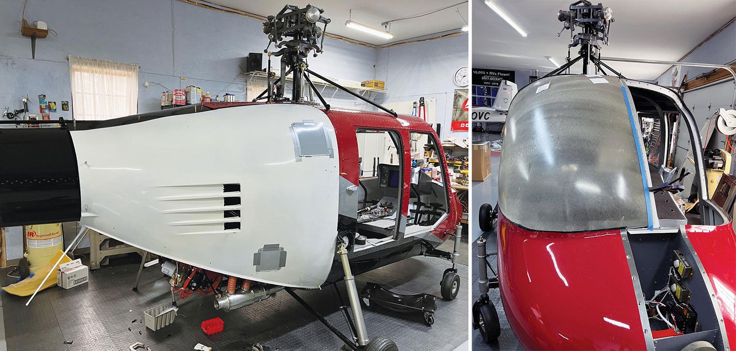
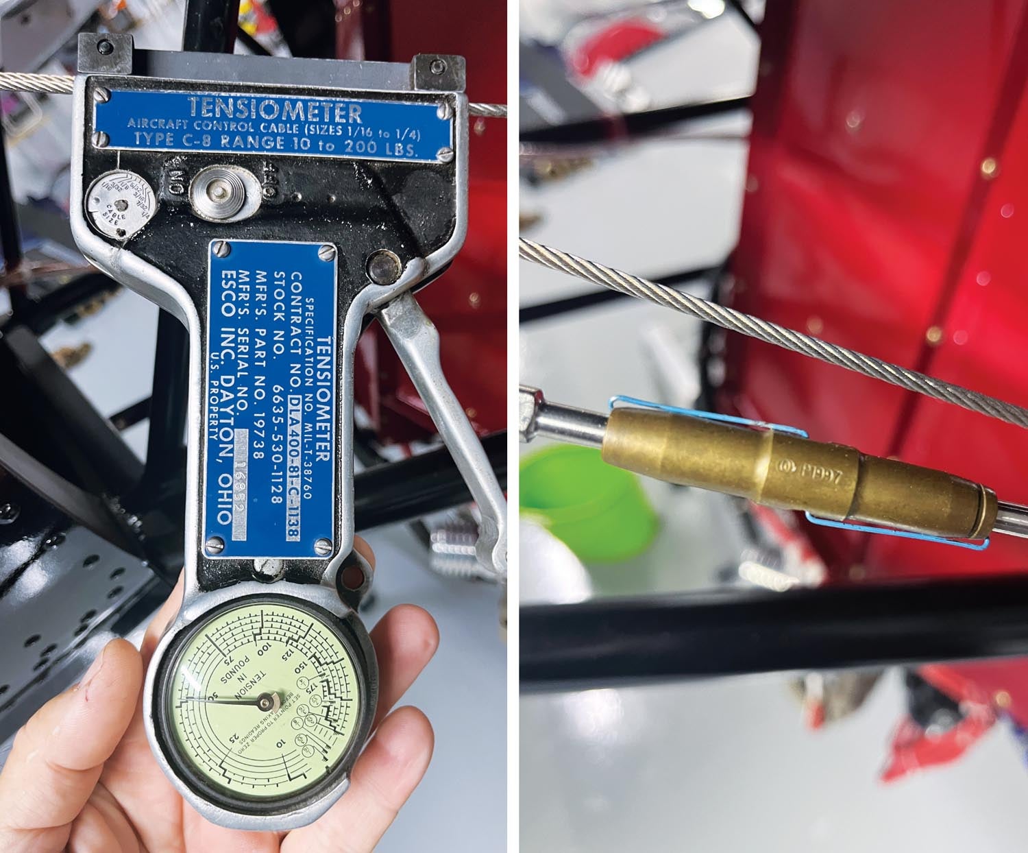
It was now starting to look like a helicopter! I installed the tail rotor, adjusted the tail rotor cables for the required 45 to 50 pounds of tension and locked the turnbuckles into place with clips. The next step was to rig the tail rotor blades for the proper deflection settings. That all went very well.
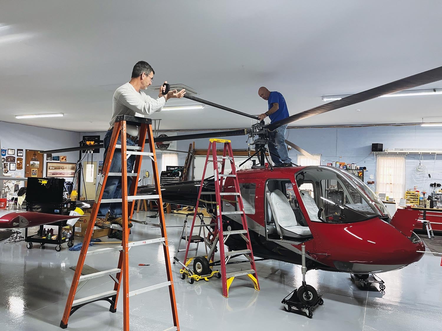
Finally, it was time to put fluid into all the systems, such as oil, brakes and fuel. The fuel bladder took 57 gallons as advertised, and I calibrated the fuel quantity system as I added the fuel in 5-gallon increments. So far, no leaks! When it came time to install the main blades, my neighbor, Steve Vihlen, lent a hand. Surprisingly, they go on easily, held in place by one big locking nut at the root. It was almost anticlimactic! Probably the most stressful part was tightening the main rotor head nut, affectionately called the “Jesus nut,” to the required 300 foot-pounds, while standing on ladders.
Carol now focused on the interior, and things really started to get inspiring. She has done all the interiors for our aircraft, and I’ve certainly been pleased with them. From what I could see in the works, this one is going to be better than all the others. I’ll leave the interior and first engine starts for the next column.
You might have heard that I’m already flying the Hummingbird and things are going well. The fun factor is alive, and hopefully we will make AirVenture, where we will look forward to seeing many of you. We are supposed to be on display in the Lycoming exhibit, so come by and see us!


