In the April 2025 issue of KITPLANES, Eric Stewart wrote a cool article showing how he used 3D printing to make mold forms for carbon fiber parts. In the epilogue to his story, Eric mentioned how one can jump into this technology by combining a cheap 3D printer with SolidWorks software, which is available to EAA members.
My own articles are often illustrated with sketches that have been CAD-generated. The particular software I use, Solid Edge, is available to EAA members to download for free.
I can’t speak to the specifics of SolidWorks, but I can tell you, from over 25 years of using Solid Edge, that modern 3D CAD software is amazing! Before Solid Edge, I was a 2D AutoCAD user (funny how only drug addicts and software people are called “users”). My AutoCAD experience was typical. I was self-taught and, after about five years, I was pretty comfortable with the software. Not 100% proficient, but comfortable. At the time my impression of 3D design software had been tempered by an experience I had when the local city college ask me to jury a design competition among student teams from their Pro/Engineer (aka Pro/E) class. At the end of the semester, none of the teams, in my opinion, had accomplished much. I deduced that, since it took me five years to figure out simple 2D AutoCAD, 3D must take forever.


A while later, a friend of mine invited me to a “free lunch” demo of Solid Edge. I assumed it would be an afternoon of arcane commands and bewildering procedures. But what the heck, it was a free lunch.
About 10 minutes into the demo, I was amazed at the simplicity and intuitive nature of Solid Edge. I was sold on Solid Edge. In less than a week, I had breezed through the essential tutorials and was designing parts and creating virtual 3D assemblies, which, by the way, include the ability to simulate where to “weld” things. Way cool. Another huge benefit was, with the click of a mouse, I could automatically output all the drawing views necessary for our patent filings: front, rear, right, left, top, bottom, and isometric. That saved a ton of dough with our patent attorney.

A few years later, when 3D printing became commercially viable, we hit the ground running when it came to making parts. Solid Edge, like all 3D software, can export design files to any format for 3D printing (typically STL, which stands for stereolithography).
The user interface for Solid Edge has evolved dramatically since I started using it in 2004. The software is more powerful and in some ways, a bit more complicated to learn than the super-easy version I started with. But I reckon it’s still infinitely easier than an old-school 2D program.

A huge advantage today is the vast array of online tutorials—and the fact that as an EAA member, you can download Solid Edge for free or SolidWorks for $24. From what I understand it’s the full software but doesn’t come with support for upgrades.
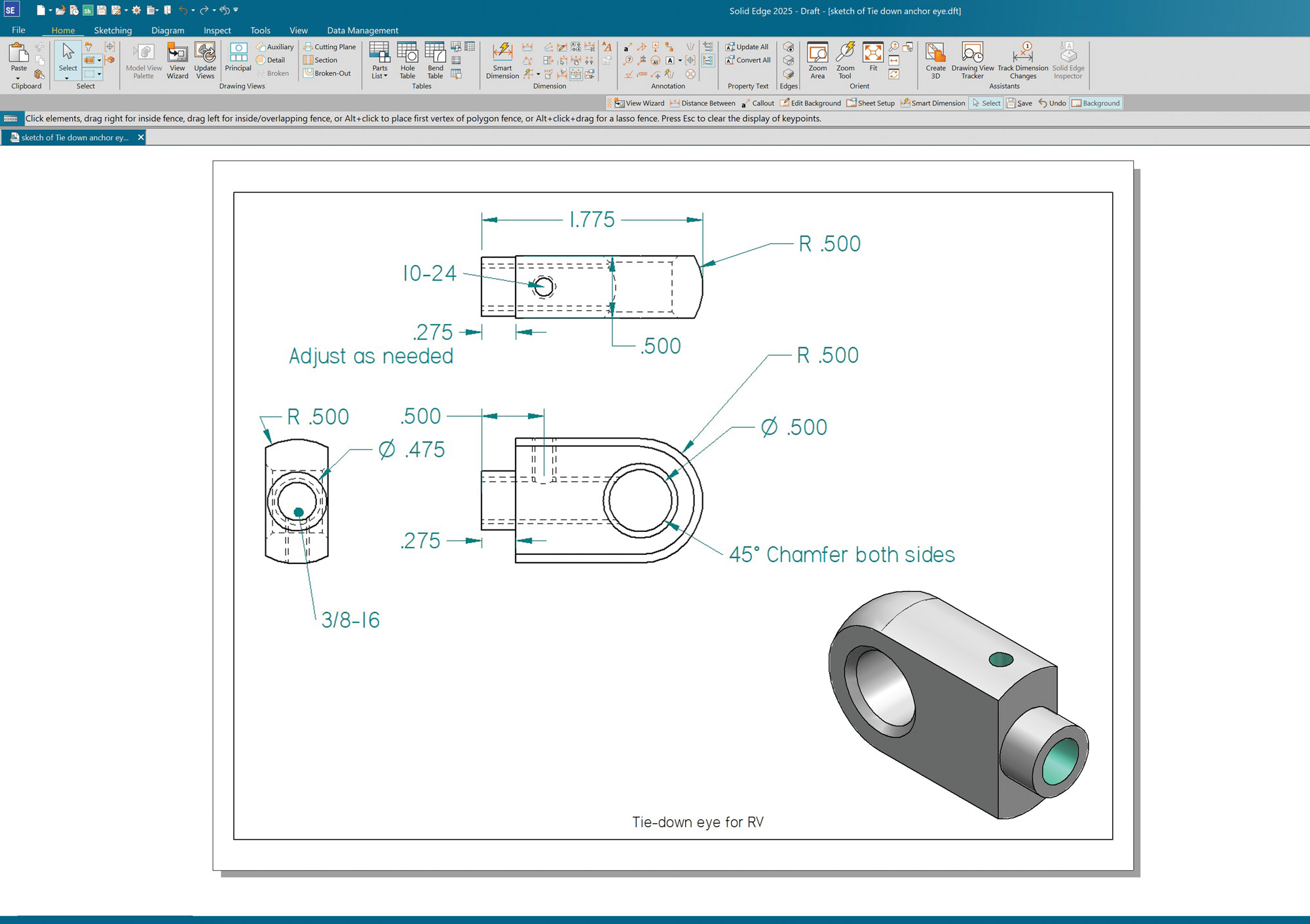
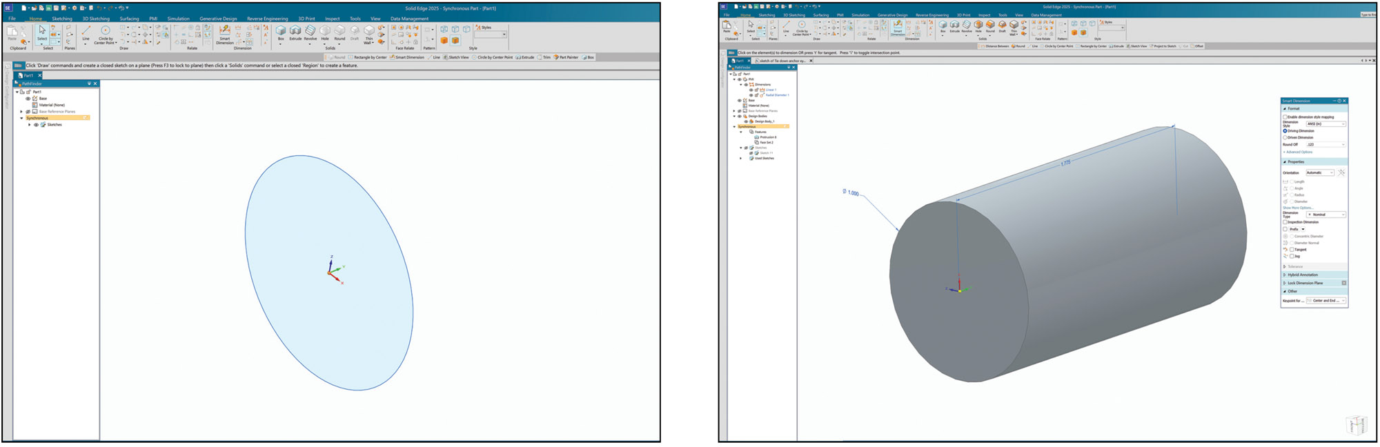
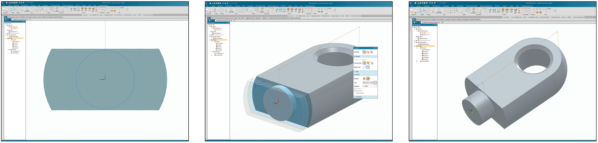
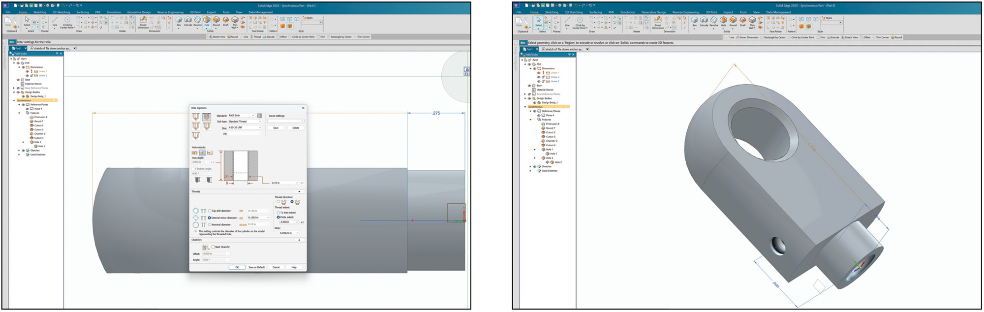
I put together a sampling of screenshots to walk through how rapidly a basic part—Steve Cogswell’s tie-down eye from the December 2022 issue—can be modeled and then set to paper for the machine shop using Solid Edge. The same goes for designing and printing 3D parts or molds. The only real difference is you may have to open the design file in preprocessing software so it can be used by your specific 3D printer.


