Last month we began our discussion of the structural layout of the wing with a look at externally braced wings. We now turn our attention to cantilever wings.
The majority of modern airplanes have cantilever wings because the drag penalty of external wing bracing is excessive for their mission.
On a cantilever wing, all of the loads are borne on structural elements that fit entirely within the airfoil contour of the wing. The wing will incorporate one or more full-span spars that carry the primary bending load.
There are two approaches to giving the wing sufficient torsional stiffness to withstand the torsion produced by the ailerons, flaps and the other aerodynamic forces that tend to twist the wing.
It is possible to use a single tubular or box spar that is stiff enough in torsion to carry the twisting loads as well as the wing bending. This approach has some advantages, particularly if the wings need to be easily removable for storage or transport (as is the case for most sailplanes), but it tends to be heavy because of the need to torsionally stiffen the primary bending spar.
The more common approach is to use at least two spars. The ribs and the wing skin span the area between the spars. The combination of the spars, ribs and skin form a lightweight, torsionally stiff box structure (commonly called the wing box).
For wing structure typical of general aviation airplanes, the forward spar is placed at or near the point of maximum thickness of the wing and carries all or most of the wing bending moment.
At the fuselage side, the designer has a choice of attach concepts:
The first attaches the wing to the fuselage only at the main spar with a single attach system that carries the lift, bending and torsion.
The second approach attaches both the main spar and the rear spar to the fuselage. The main spar then carries the majority of the lift and bending moment, and the rear spar is either shear-tied to the fuselage or carried through like the main spar to transmit the wing torsion into the fuselage.

Wing Carry-Through
By far the biggest configuration integration task for an airplane with a cantilever wing is carrying the wing bending moment across the fuselage. The configuration must incorporate a carry-through structure that can withstand the full bending moment generated by the wing.
For the majority of airplanes this means that there will be a carry-through structure inside the fuselage that is the same depth as the wing main spar.
It is possible to use an arrangement where the wing spar is butt-joined to a very stiff ring frame that carries the bending loads around the outside of the fuselage. This arrangement is called a side-tie wing, and it is used on some military fighters to carry the wing bending loads around the ducts and engine bay for jet engines incorporated inside the fuselage. Side-tie wings are rarely, if ever, used on other types because the ring frames must be very strong, and hence very heavy, to carry the wing bending around the central hole in the frame. A side-tie arrangement will always be significantly heavier than a full-depth carry-through and is therefore only used when major components of the configuration cannot be integrated with a carry-through design.
Fuselage Integration
The carry-through structure of a cantilever wing is as deep inside the fuselage as it is in the wing root. This means that somewhere along the length of the fuselage, a cross-ship path is needed for the carry-through.
The position of this structure is not arbitrary. The main spar of the wing is at or near the chordwise position of the maximum thickness of the wing. As we have already seen, the wing must be located on the fuselage in a position that puts the wing aerodynamic center close to the flight CG of the airplane. This leaves the designer relatively little freedom to move the carry-through forward or aft.
The primary issue the designer must resolve is the relationship between the wing carry-through structure and the occupants of the airplane. In order for the airplane to balance properly, the variable load (people, cargo and fuel) must usually be centered about the flight CG to minimize CG travel. This tends to put the occupants of the airplane in approximately the same fore-and-aft position as the wing carry-through structure. The designer must devise an arrangement of seating and wing position that allows the people to sit in the airplane and the wing structure to carry through intact. This integration presents different challenges for low-wing and high-wing configurations.
Low Wing
On a low-wing airplane, the carry-through structure is at the bottom of the cabin. On a four-place airplane with two rows of seats, the spar can run between the rows. The front-seat occupants (pilot and right-seat passenger or copilot) sit either ahead of or on top of the spar, and the rear-seat occupants are behind the spar. On a two-seater, it’s common to run the spar just ahead of the seats so it passes under the crew’s knees.
On larger, pressurized airplanes like airliners and bizjets, it’s common to run the carry-through structure entirely below the cabin to keep the fuselage pressure vessel cross section circular and then add fairings to guide the airflow around and under the wing box.
Any arrangement that runs the wing carry-through structure under the seats or the cabin will likely force the fuselage to be deeper than the minimum height required to accommodate the occupants. Sometimes the fore and aft position of the carry-through can be adjusted slightly by using changes in wing planform, wing sweep or airfoil shape to move the position of the spar at the wing root forward or aft relative to the aerodynamic center of the wing. This is a relatively limited option, but sometimes a few inches can make a big difference in the integration of the fuselage.
High Wing
It’s harder to integrate a cantilever wing carry-through structure on a high-wing airplane than a low-wing one. On a high-wing airplane, the spar must cross on the top of the cabin. This tends to put it in conflict with the heads of the front-seat occupants on a four-place airplane and in front of the crew on a two-seater.
Either of these situations presents the designer with a problem. Obviously, the spar cannot pass through people’s heads. Even if the spar is forward of the crew’s heads, it’s still a problem because it will be in front of their faces, obscuring forward visibility.
The designer has two choices: Make the fuselage deeper so the wing carry-through goes above the crew’s heads, or try to get the front-seat occupants’ heads forward of the carry-through.
Deepening the fuselage works well to help balance the airplane because it gives the designer freedom to move the wing fore and aft relative to the fuselage without conflicting with the occupants. The downside of this approach is that the fuselage will be a little heavier and draggier than it would be if the extra depth was not required.
Moving the front seats ahead of the wing carry-through allows the fuselage depth to be reduced, but introduces balance issues. The wing spar tends to be about at the flight CG, so moving the occupants forward places their weight ahead of the CG and tends to make the airplane nose-heavy.
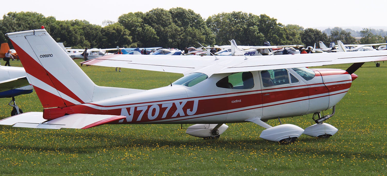
This can be alleviated with proper design. A wing planform with a slight forward sweep of the spar, combined with an airfoil that has its maximum thickness further aft than usual, can move the spar aft just enough to allow the crew to sit ahead of the spar. The airplane will still be a little nose-heavy with heavy people in front and no one in the back, and it will have a bit more CG travel than if the spar went over the top of the cabin. The mild nose-heavy condition can be countered by providing a horizontal tail with a bit of extra control authority to trim the airplane when loaded to its most forward CG. Cessna used this approach on the Cardinal, and this need for extra tail power is why the Cardinal has an all-moving horizontal tail as opposed to the conventional fixed-tailplane plus elevator tail found on all of the other high-wing Cessnas.


Interesting about the cardinal. A question I have is what is the disadvantage of a full flying tail. I assume weight and complexity but they seem trivial compared to the advantage.
And with a full flying tail you could go supersonic,,,,,, you know,,,,, if you wanted too?
A picture is worth a thousand words, and I sure wish your descriptions were backed up with a few pictures or diagrams. As it is I still am confused about this form of wing attachment.
Comments are closed.