In general, there are two ways to increase the maximum lift of a wing. The first, as we have been discussing the past couple of months, is to add lift at a constant angle of attack by increasing camber using a flap system. The second way to increase the maximum lift capability of a wing is to delay the stall to a higher angle of attack.
There are several types of high-lift devices that can do this. These devices can work either independently or in conjunction with a flap to provide higher maximum lift. They produce little or no change in lift at a constant angle of attack, but allow the wing to fly at a higher AOA to make more lift.
A wing lifts by deflecting the stream of air flowing over it down. As the air encounters the wing, the wing turns it so that it ends up moving downward relative to the free stream. The higher the angle of attack, the greater the deflection of the airstream. The biggest change of direction of the airflow happens near the leading edge of the wing.
As the air approaches the leading edge, it is split by the wing so that some air flows under the wing and some air flows over it. The air going over the wing must make a turn around the leading edge in order to flow smoothly over the wing. The higher the angle of attack, the more the air must turn.
Eventually the turn becomes more than the air can sustain and the flow separates from the upper surface of the wing, producing a stall.
All of the devices that increase stall angle of attack work by helping the airflow negotiate this initial turn.
Leading edge devices or stall angle-of-attack-delay devices are used on several classes of airplane. On aircraft with high wing loadings and powerful flap systems, such as airliners and some business jets, leading edge devices are used to keep the leading edge from stalling prematurely so the wing can develop the full lift potential provided by the flaps.
In the general aviation world, leading edge devices show up for one of two reasons. The first is to get STOL capability. The second is to help provide safe lateral directional characteristics and stable roll damping when the airplane stalls.
There are several types of devices that can be incorporated at or near the leading edge of the wing to help the air make the turn. Some can be retrofitted to existing wings, and some must be designed into the wing from the beginning. We will start by looking at two relatively simple retrofittable systems.
Leading Edge Droop
One way to help the air negotiate the path around the leading edge of the wing is to make the turn longer and gentler. We can do this by drooping the leading edge so that it is pointing more into the oncoming airflow at higher angles of attack and then provides a longer, larger-radius curve for the air to flow over as it moves onto the upper surface of the wing. This leading edge droop camber can be designed into the wing from scratch or can take the form of a cuff attached to the existing wing to change the shape of the leading edge.
Leading edge droop cuffs are a common component of STOL retrofit kits available for a wide variety of single engine airplanes. The biggest advantage of the leading-edge droop cuff is its simplicity. Regardless of whether the droop is designed in from the beginning or added as an external component, it is a fixed geometry and the shape of the wing does not change in flight. It is no more mechanically complex than any other wing and has no actuators or other moving parts.
The potential disadvantage of the leading-edge droop cuff is that it fundamentally changes the shape of the airfoil of the wing. Adding the droop redesigns the airfoil of the wing. The new design is shifted toward a shape that is more optimized for low speed and high angle of attack flight than for high speed, low angle of attack flight in cruise.
It’s common for an add-on leading edge droop to cause additional cruise drag and exact a cruise speed penalty in return for the improvement in maximum lift and reduction in stall speed that it provides. For many light-airplane STOL missions this drag penalty is small enough to be acceptable, and the ruggedness and simplicity of the fixed leading-edge droop is a significant advantage.
Vortex Generators
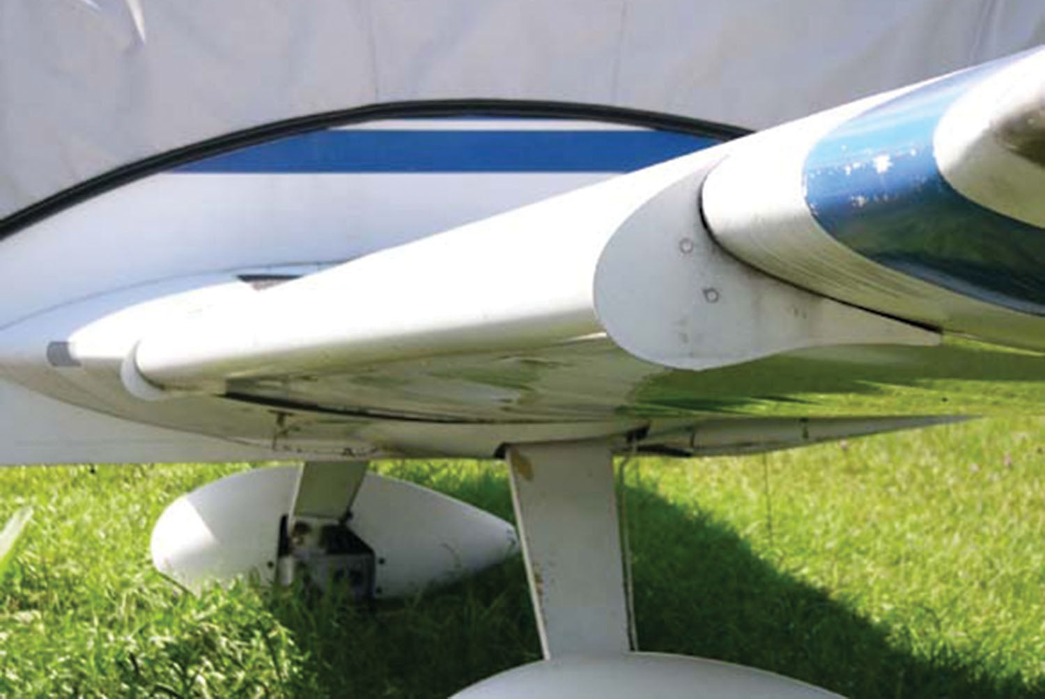
Vortex generators have become extremely popular as a retrofittable device to increase angle of attack at the stall and reduce stall speed. STC’d vortex generator kits are available for a wide variety of certified airplanes.
Vortex generators are small blade-like devices that protrude upward from the surface of the wing. The blades are set at a yaw angle relative to the free airstream so that there is a constant angle of attack on the blade of the vortex generator. The upper edge of the vortex generator acts like a miniature wingtip and sheds a vortex very similar to the tip vortex of a lifting wing. This vortex streams aft from the VG along the wing skin. The vortex entrains high-speed air from above the wing and pulls that air down to the surface. This high-energy air can stay attached better than air that has flowed against the skin all the way from the leading edge. The extra energy in the entrained air delays the stall by energizing the boundary layer and keeping it attached.
Properly placed vortex generators allow a wing to go to a higher angle of attack and develop more maximum lift before stalling. They work differently than the leading-edge droop. The VGs don’t change the shape of the turn the air must negotiate. Instead, they help reenergize the flow after the initial turn around the leading edge to help keep it attached.
Vortex generators used to increase maximum lift are not placed at the extreme leading edge of the wing, but they are usually well forward of 25% chord. The proper position is a compromise between maximum lift and cruise drag. Moving the VGs forward increases maximum lift, but also increases cruise drag. The optimum VG position is the farthest aft location that produces the needed improvement in stall characteristics.
The primary advantage of vortex generators is that they are simple and easy to retrofit without making any fundamental change to the shape of the airplane. This is why they are commonly used as fixes for aerodynamic issues that appear after an airplane is complete and changing the geometry of the airplane to improve the airflow is difficult.
The primary disadvantage of vortex generators is that there is a certain amount of drag associated with each VG. Accordingly, an optimized installation will use the smallest number of VGs needed to get the target improvement in maximum lift. If this is done right, the drag penalty can be quite small, in part because there is some favorable interaction between the VGs and the wing even in cruise.
The total drag increment is often significantly less than the sum of the drag of all of the individual vortex generators because the vortex generators can improve the flow downstream of the devices. The VGs often reduce the drag of the wing itself, but this drag reduction is almost always less than the drag of the devices themselves. For a well-engineered VG installation, the total drag of the aircraft is at worst only slightly higher than the airplane without the vortex generators.
An important exception to this is if the wing has an airfoil designed to have significant laminar flow. The vortex generators will trip the boundary layer from laminar to turbulent, and no laminar flow will exist aft of the vortex generators. This is important because in order to significantly delay the stall, the vortex generators must be well forward on the wing while a good low-drag laminar flow airfoil will be designed to have laminar flow to at least 40% to 50% of the chord. The vortex generators will trip that flow well forward of that and dramatically reduce the amount of laminar flow on the wing. If this happens the drag penalty of the vortex generator installation will be quite large because the loss of laminar flow will increase the drag of the wing itself quite significantly.
Next month we will look at another class of leading edge high-lift device: slats and slots.


Barnaby,
Many years ago Dr. Don Ward, of Texas A&M, was consulting us on a spin recovery problem on a modified Cessna P210.
He cautioned us that mods used to delay flow separation, specifically drooped LEs, could also lead to a spin becoming unrecoverable, even though it might be difficult to get into the spin initially..
Thoughts?
Wing wash-out can be used instead of drooped leading edges to ensure the stall starts at the root, and not at the tip.
A slightly more cambered airfoil, which can be helpful at low speed, can work quite well overall if the flaps and ailerons can be trimmed upward to minimize drag at high speed. Like many flying wing’s airfoils!
Can you include strakes in your discussion as well. I realize they are more like VG’s than high lift devices. Some people argue VG’s don’t enhance stall speed on certain aircraft but they do provide better control at lower speeds to improve landing characteristics. So many different ways to get value from them situational to each pilot’s preference.
Are there benefits to using vg’s and drooped leading edge together?
Comments are closed.