OK, so we’ve got that 100-watt solar panel firmly bolted to the hangar roof. Let’s take the other pieces that we have to have and would like to have in the order of wiring them together.
If you recall, I said that wiring from the solar panel should be mechanically separated from the sharp edges of the metal hangar. While I showed how to use a cable clamp secured by a wood screw into the edge of the plywood solar panel mount on the roof edge, that technique wasn’t available to me as I passed the cable through the vertical hangar walls. Nor was it available to me on the small 15-watt aircraft battery charger I installed on the front edge of the hangar. I had to rely on plastic tubing to protect the wires.
By far the easiest of the various types of plastic tubing to use, especially where the wiring already has connectors fastened to them, is split wire loom (also sometimes called split tubing). This is a corrugated, easy-to-bend plastic tube that has been slit from one end to the other so you can simply pull the slit open, insert the wire, and the tubing is stout enough to close the slit up when you are done. The plastic used is very strong; don’t try to use scissors to cut it. Use big wire cutters instead. Split wire loom is available on Amazon and at most major hardware chains (Ace, Home Depot, etc.) as well as local electric supply and hardware stores.
Once you get the connector wires protected from sharp edges, the next order of business is to connect them to the solar array regulator. My first thought was to use standard home wiring (Romex et al.), but then I considered that the insulation and wiring was sized for at least 220 VAC, and the outer sheath was designed for in-wall use that sometimes contains small furry critters with sharp teeth. In other words, overdesigned for solar. What I wound up with was sort of, not exactly, what I wanted, but it will do since I’m only using it for relatively short distances and relatively low currents. Where I will wire up fairly hefty current equipment (say, over 10 amps), I’ll use some of the good stuff from my local hardware store. Remember, that 100-watt solar panel is only going to be pumping at most 8 amps into the regulator (at 13.2 volts) and AWG 14 wire should certainly handle that sort of current.
Oops!
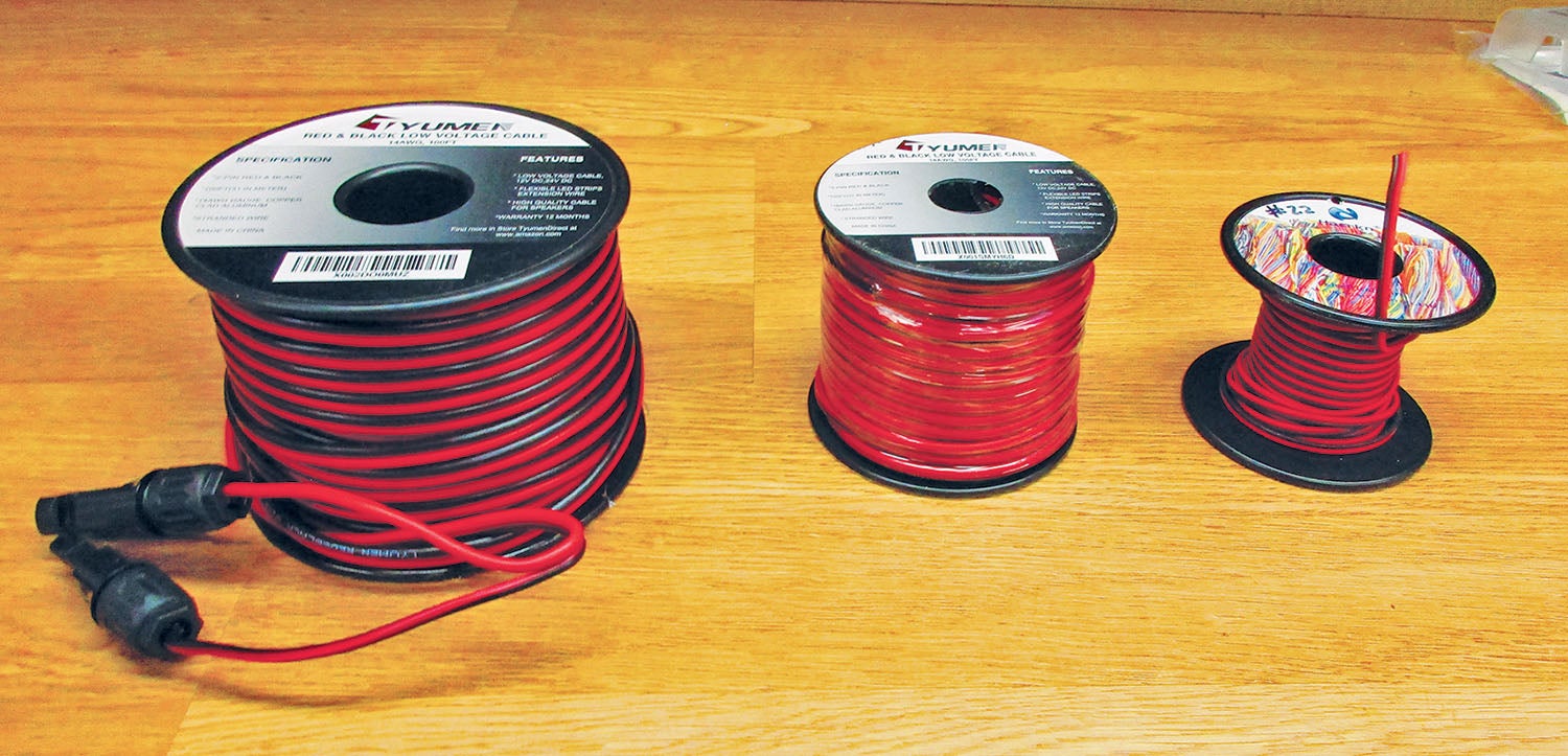
Now for my first minor stumble. Amazon has some really nice two-conductor, red-and-black wire, all the way from AWG 10 to 22 and relatively inexpensive (much less than a dime a foot). I read all the specifications for this particular brand and size (Tyumen 14 AWG) and either I missed it or it wasn’t part of the specifications that it was copper-coated aluminum wire (CCA). That’s going to have to be part of the consideration where I use this wire as well as what size is appropriate. The CCA soldered up just fine when I put the connectors on it, but then I found some very tiny print on the reel that said copper-coated aluminum. It is somewhat telling that Amazon is carrying the Tyumen in smaller gauges but has discontinued the #14.
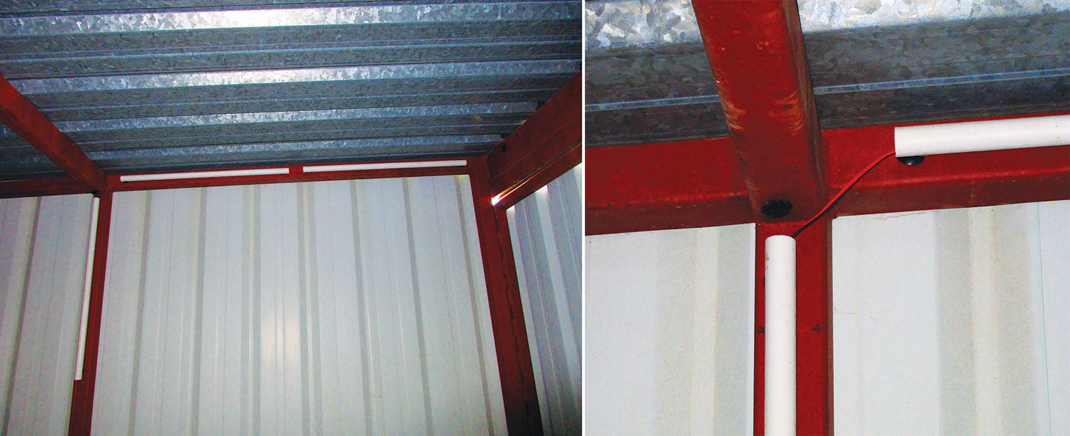
Somehow that solar panel wire has to get from the top of the wall where the solar panel connectors come inside the hangar down to the regulator. It has to be protected, at least somewhat, from falling down. It also should have some sort of protective shield over it to keep away critters with sharp teeth that somehow find their way into our hangars. To boot, it should be flexible enough to accommodate additional wires that somehow didn’t find their way onto the plans when we first drew them up.
High voltage (30+ volts) needs metal piping (conduit), but 12-volt doesn’t have such a restriction. I tried everything I could think of—plastic tie-wraps, waxed twine, hot glue—and nothing really fit or looked good. I tried using PVC water pipe with these physical fasteners, but the pipe kept slipping down or dangling at some cattywampus angle.
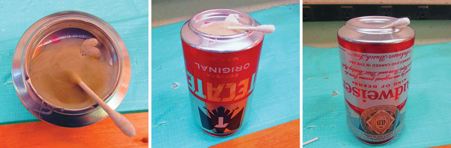
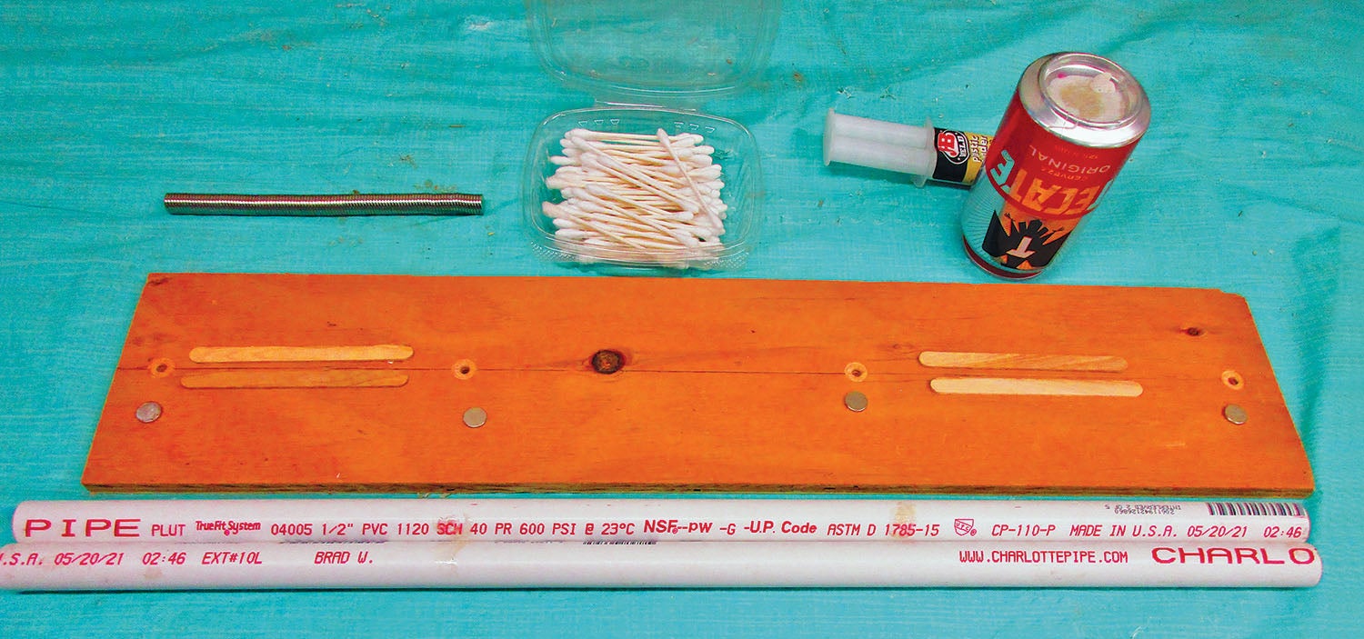
Then I discovered “redneck conduit.” In my college classes I used small ferrite magnets to demonstrate simple motors and other show-and-tell projects. Voilà! Glue magnets to that PVC water pipe and let them fasten themselves to the steel structure and walls of the hangar. Simple. Cheap. Removable or repositionable if necessary. There were a few preliminary (and messy) problems attaching the magnets in straight alignment on the water pipe, but nothing that J-B Weld’s KwikWeld epoxy and a simple plywood jig can’t handle. I used 2-foot-long sections of pipe with a 6-inch gap between pipe ends for future wire drops for future power boxes. Four magnets per length of pipe seems to be the best compromise between holding power and cost. (Hint: 12mm diameter neodymium magnets are four to 10 times stronger than ferrite and cost about the same—two bits each. A ½-inch spade bit makes a perfect pocket in plywood for a 12mm magnet.)
J-B weld says that heat hastens the epoxy dry time. My lab thermometer showed 107° F outside, and the epoxy fully set up in an hour (maximum). Remember to rough up the smooth PVC where the magnets are going to go with a wire brush or sandpaper.
Brains in a Box
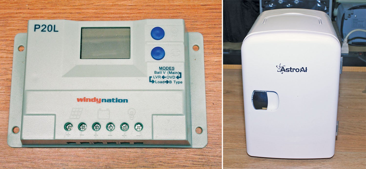
The “brains” of the entire HOG system are contained in a little box about the size of a Big Mac hamburger with the sides and ends chopped off to make it rectangular. It takes the unregulated input voltage of the solar cell (about 18 volts in full summer sun) and converts it to 13.2 volts to charge the solar power supply battery and simultaneously limits the output load current to 20 amps. If I tried to tell you about all the bells and whistles on this box, I would be into the April 2022 issue. You can learn more about the WindyNation P20L regulator. Note that there is a 30 amp unit also available with all of the features of the 20 amp regulator plus a few more goodies if you need more current.
In concert, there is a 100 amp-hour battery designed to work with this whole solar cell regulator setup. To see the specifications go here and look for the BAT-RA12 series. One caution: The terminals are a nonstandard 5/16-inch thread and will need special wire lugs available from all the sources mentioned for the split wire loom.
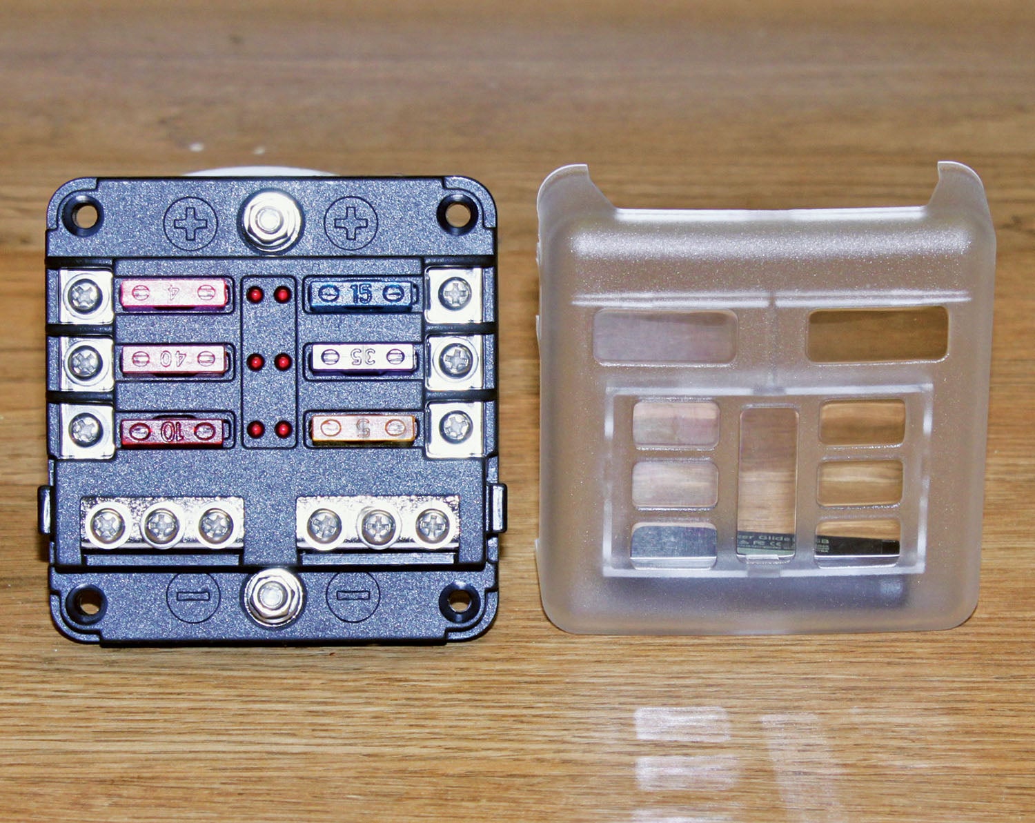
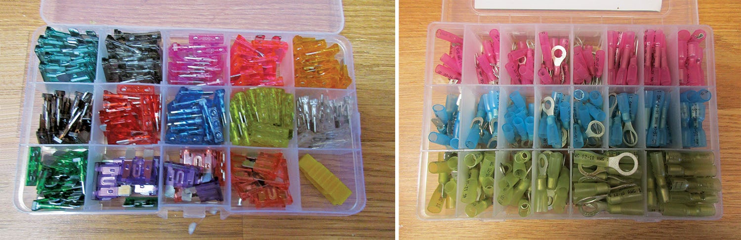
There’s also a relatively inexpensive ($20) 12-volt fuse block that uses standard automotive blade fuses. There are 6-, 9- and 12-circuit fuse boxes available. I looked and could only find five circuits I needed to fuse, so I got the 6-fuse box. I also bought a box of extra fuses. (Available at Amazon or your local well-stocked automotive parts store.)
A Few Surprises
Now for the stuff that didn’t work as expected…the two lab failures (or at least disappointments).
1. The refrigerator will hold six 12-ounce beverage cans. That’s fine. The refrigerator will run on either 110 VAC or 12 VDC. That’s fine. The refrigerator will cool down to 60° F below ambient. That’s fine. The refrigerator works on Peltier effect semiconductors. Without going into a long song and dance, Peltier effect semiconductors work by passing a current through a diode and letting one end of the diode get spit-sizzle hot and the other one colder than a witch’s breastbone. The hotter side is exposed to room temperature air and dissipates the heat into the atmosphere (i.e., the hangar). The colder side is enclosed in the refrigerator and cools 100° F hangar air into 40° beverage cans. So far, so good. However, it takes about 3 amps of current to do this cooling. The problem is that it takes this amount of current continuously. That is, no matter how cold the fridge gets, it takes 3 amps. There is no thermostat to say “enough, already.” It just keeps sucking 3 amps no matter how cold it is inside the fridge.
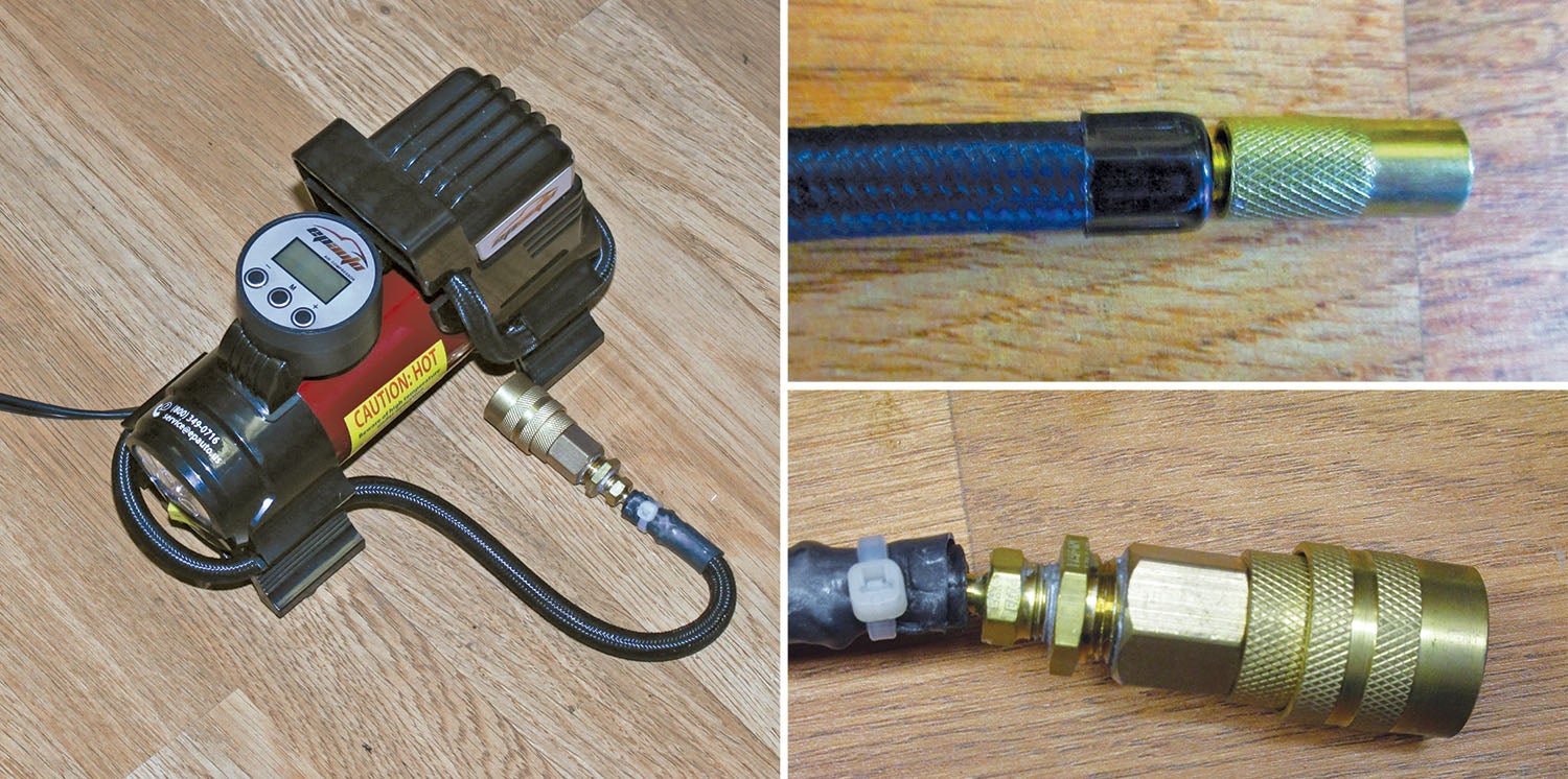
2. The air compressor will give you as much pressure (up to about 100 psi) as you want on about 10–15 amps of current. Once. Once the compressor gets up to that pressure into your chosen vessel, it shuts off. It will not restart unless you disconnect it, reset it, and reconnect it. Not much good for an engine compression test of 80 psi that requires a continuous supply of constant air pressure. Another down-stream pressure tank? Another type of compressor? Don’t know yet.
I’m going to back off from HOG for a month and give you a whole bunch of tips and tricks I’ve learned over 61 years of avionics and wrenching beginning in eighth grade. If you would like to see where I cut my teeth wrenching and radioing on aircraft, see this. It was an hour’s bike ride from my home in Lemon Grove, and I spent hours there on weekends asking questions and cleaning greasy parts. Until then…Stay tuned…


It sounds like that six can fridge needs a thermostat – on at 45F, off at 40F, or there-abouts —–
Comments are closed.