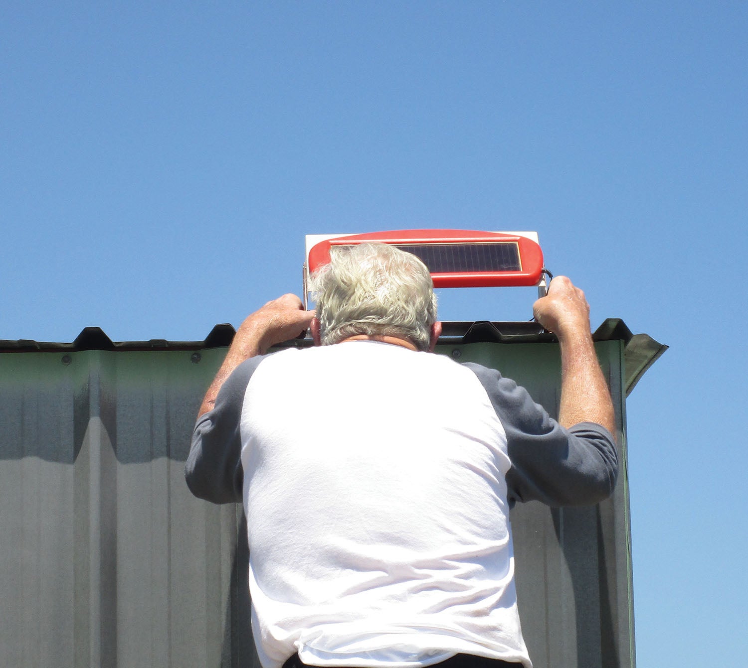
Putting it on the hangar roof and wiring it to the airplane, that is. This is the first of a whole lot of things that are scheduled for hangaring in the next month or three. If you recall, one of the things we want to do is to keep the airplane battery charged with solar power. To ease you into the program and prove to yourself that this is a feasible project for you, too, I decided to make this one very basic and yet use all of the tricks and techniques that we have developed over the last few months.
The drill here is to use the following components:
- A relatively inexpensive Harbor Freight solar panel that puts out only a watt and a half.
- A cheap but reliable connector.
- Some relatively inexpensive #24 zip wire to wire up the unit.
- A project box that we used to be able to get at (sniff) Radio Shack but is readily available at most of the online as well as brick electronic stores.
- A couple of small terminal blocks.
- A handful of electronic components from your favorite online parts distributor.
By the judicious use of coupons and specifying parts that say “free shipping” on them, I think I’ve been able to do this whole project for about $25. Complete.
Ohm and Watt told us a long time ago how much current we can expect for a watt-point-5. Let’s see now. Power is voltage times current, so if we know voltage (13.6 AGM battery charging voltage) and wattage (1.5 as we said above), then current should be power (1.5) divided by voltage (13.6), and we come up with 0.11 amperes (amps) or 110 milliamperes. That may not seem like a whole lot of current, but don’t forget that Old Sol works at least 8 hours a day in the winter and 12 hours a day in the summer. For free, day in and day out. They say that Sol will keep doing that for a few hundred million more years, and that is long enough for me.
A little more mental math with amp-hours (battery storage power), and a worst case of 8 hours shows that we will be putting just a little short of an amp-hour a day every day into the battery in winter and a little more than an amp-hour a day in the summer. Given that you will be putting this charger onto your airplane just after you fly it and that the battery is nearly fully charged at this point, all this little gem has to do is combat the self-discharge of the battery overnight, and an amp-hour is more than sufficient to complete that task. Every day. Mostly rain or shine.
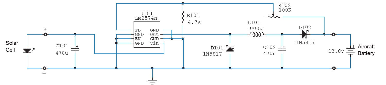
A couple of more things that will complex up the issue: The solar cell in dim light unloaded or in strong sunlight loaded puts out between 16 and 20 volts. If we use a plain old linear regulator (as we discussed in the May 2020 issue), we will be throwing away as heat the difference between 16–20 and 13.6 volts at the same current. That is measurably less than a watt.5 into the battery. What we need is a power converter that takes the 16–20 volts at full load current and converts it to power at 13.6 volts. High voltage at low current translates to lower voltage at higher current to keep the power the same. The only real way to do this is with a switching regulator, and a good cheap regulator is the old reliable LM2574. As bulletproof as they come and about $1.50 at most online stores. Two capacitors, two diodes, one resistor and one small trimpot and you are home free (or five bucks at the outside).

So, we built this little power-converter controller and a fixture to let us set the solar panel to the optimum angle. Guess what? Theory said that we would be putting about 110 mA into the battery. Allowing for 10 mA to light the “on” light in the chassis, we had just a little more than 100 mA into the battery, which almost exactly matched the theory.

“Putting” it on the hangar involved just a bit of compass work. As we said previously, true south is not necessarily magnetic south. In this case 180° true = 167° magnetic. And once again, serendipity fell into my lap. For whatever reason (since our runways and taxiways are 25/07 magnetic) the hangars were installed due north/south. Within 1°. Every now and again the blind pig picks up an acorn.
Running the wires into the hangar, I just needed to observe that rainwater is going to follow wires and that drip loops are necessary.
The manufacturer has a lot of comments on this little solar panel, and most of them go something like, “I put it on my tractor battery in the fall and it fired right up for spring plowing.” Note that there is no mention of a voltage regulator, just hooking the panel right up to the battery.
On the other hand, the manufacturer’s data sheet says (in two places) that to use this solar panel for battery charging, you need to have a voltage regulator. This may be the legal department putting in a belt-and-suspenders clause or it may be the engineering department that thinks a regulator is necessary to keep from overcharging the battery.
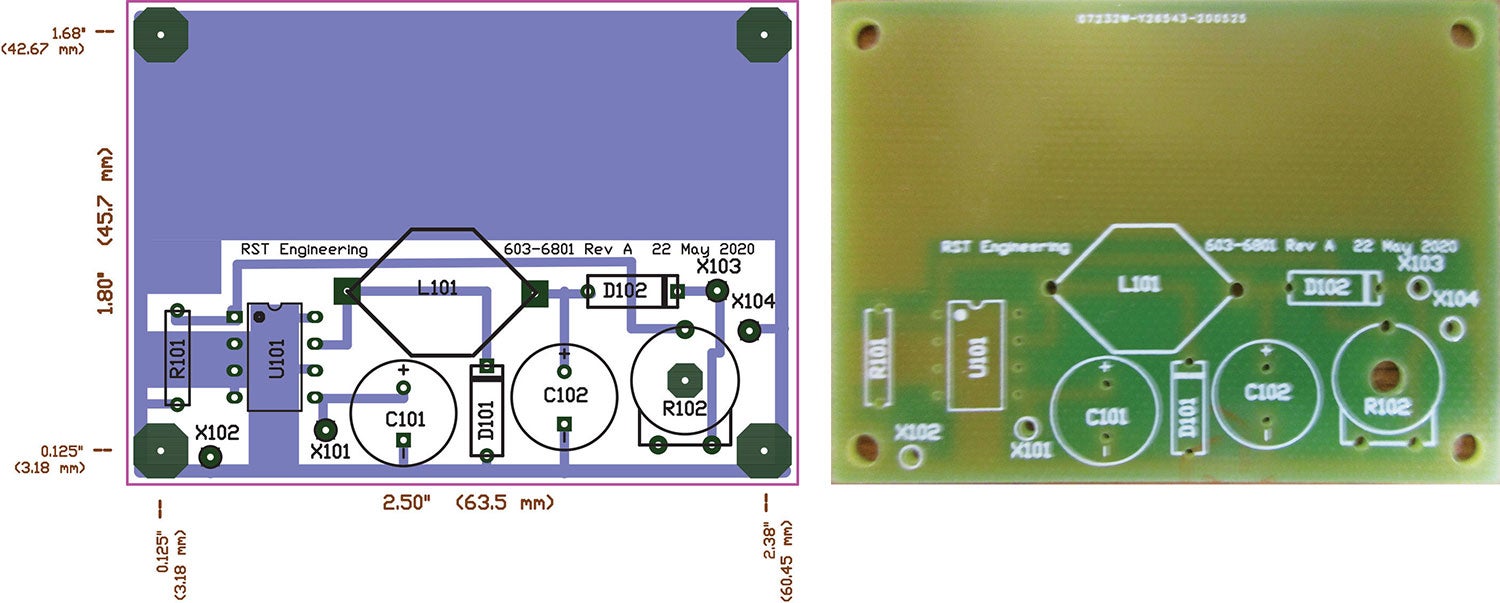
My opinion? A tractor battery for $25 is one thing, but an aircraft battery for $250 is quite another. The charger regulator circuit shown in the images can be assembled for about $10–$15 in parts including a PC board made by one of several companies that specialize in one-off prototypes.
The regulator design is a modification of the circuit I showed you in the May issue, only this time with a smaller half-amp (500 mA) IC that doesn’t need any heat sinking. My measurements shows that the unit is roughly 95% efficient as it should be with only a watt and a half of energy to start with. We were getting just shy of 100 mA into the battery, and that is about exactly what we said we were going to do.
More later when we install the really heavy-duty installations like lights, inverters, compressors and the like. Until then…Stay tuned…
Photos: Jim and Cyndi Weir.


