For the past few months, we’ve been covering various aspects of longitudinal flying qualities, but pitch is not the only axis we must concern ourselves with to make the airplane fly well. Yaw and roll are also vitally important. Accordingly, we now move on to the lateral/directional stability and flying qualities of airplanes, including the effects of dihedral.
Ideally, an airplane trimmed for straight and level flight should continue in straight and level flight indefinitely. If it is disturbed, it should recover. To do this the airplane must not only be stable in pitch, it must be stable about two other axes. The first axis is the directional, or yaw axis. If the airplanes nose is yawed left or right by turbulence or a rudder input, the yaw should cause an aerodynamic yawing moment that tends to point the nose back into the wind. The second axis is the roll, or lateral axis. If the airplane is rolled from level flight, we want it to generate a rolling moment that will tend to level the wings.
Unlike pitching motions, which occur about a single axis, rolling and yawing motions are cross-coupled. When a stable airplane is disturbed in roll or yaw it will respond by both rolling and yawing, even if the initial disturbance was a pure roll or a pure yaw. The roll and yaw behavior is referred to as its lateral/directional characteristics, which play an important part in determining whether it is a safe and pleasant machine to fly. Poor lateral/directional characteristics can make precise flying difficult or impossible, and can also lead to wallowing motions that will tax even the strongest stomach.
Sideslip
When an airplane is in coordinated flight, the airstream approaches the airplane from dead ahead. If the nose is yawed away from the wind, the angle (in the top view) between the centerline of the airplane and the incident airstream is called the sideslip angle. Both yawing and rolling the airplane generate sideslip. It is easy to see how yawing the airplane generates sideslip. How roll generates sideslip is a little more complex.
If an airplane is in level flight, the lift of the airplane is acting up, the weight of the airplane is acting down, and the two forces are in balance. If the airplane is rolled, the lift is now directed in the direction of the bank, and is no longer acting in a direction directly opposite to the weight. While the lift is still acting at 90 to the span-wise axis of the airplane, the weight, which is still acting straight down towards Earth, is now pulling the airplane toward the lowered wing. This causes the airplane to slide sideways, or sideslip, in the direction of the roll. This situation will persist as long as the flight path of the airplane remains straight. In a coordinated, steady-state turn, the component of the weight acting toward the inside of the turn is balanced by the centrifugal acceleration of the airplane on its curved flight path.
It is the effect of sideslip on the rolling and yawing moments generated by the airplane that determines its directional/lateral characteristics. We will discuss each axis individually, and then turn our attention to coupled directional/lateral effects.
Directional Stability
The tendency of an airplane to swing its nose back into the wind in response to a sideslip is called directional stability. It is also referred to as “weathercock stability,” because the airplane behaves like a weathercock, which always tries to point into the wind. If the airplane tends to point its nose back into the wind in response to a sideslip, it is directionally stable. If it tends to yaw away from the wind, increasing the sideslip angle, it is directionally unstable.
Good directional stability is vital if the airplane is to have acceptable flying qualities. Nothing makes an airplane unpleasant to fly sooner than weak directional stability. If the airplane has insufficient directional stability it will be difficult to coordinate turns, and the airplane will have a tendency to wallow and wander in flight. Flying a directionally unstable airplane is virtually impossible without the aid of sophisticated (and incredibly expensive) flight-control computers.
It is worth noting that poor directional stability is a relatively common defect in homebuilt airplanes, particularly early versions of airplanes designed to go fast. Designers, in an effort to minimize wetted area, try to make the vertical fin as small as possible. Two of the most popular fast kit airplanes on the market today had their fins and/or rudders enlarged early in the life of the design. While no one has ever made a definitive statement about why this was done, I will wager that the airplanes were much more pleasant to fly after the fin-enlargement modifications.
Making the fin bigger probably did not have a significant effect on the speed of the airplanes. The amount of wetted area that must be added to a marginal-sized fin to make it an adequate-sized fin is quite small compared to the wetted area of the airplane as a whole. Also, an airplane that is directionally marginal will tend to hunt laterally and end up spending much of its time flying with some sideslip. This sideslip causes drag, so in real-world operation the directionally stable airplane with the larger fin may actually prove to be slightly faster than the small-finned machine.
Fin Effects
Three factors determine the effectiveness of the vertical fin at stabilizing the airplane directionally. The first is the area of the fin. The fin stabilizes the airplane by producing side force on the aft end of the airplane. When the airplane sideslips, the fin is presented to the air at an angle of attack. This causes the fin to develop lift that pushes the tail of the airplane sideways, away from the incident wind. This fin side force is what swings the nose back toward the wind. The larger the fin, the more force it can produce at a given sideslip angle, and the more it will stabilize the airplane.
The second factor affecting the directional stability of the airplane is the tail arm. The tail arm is the distance between the center of gravity and the aerodynamic center of the vertical fin. The stabilizing yawing moment that the fin produces when the airplane yawed is the product of the fin side force and the tail arm. Increasing the tail arm increases the lever arm over which the fin side force can act to counteract the yaw. The longer the tail arm, the more directional stability the airplane will get from a given vertical fin.
A third factor affecting the directional stability of the airplane is the aspect ratio of the fin, which determines the slope of the fins lift curve. In other words, it determines how much the lift coefficient of the fin will change in response to a change in fin angle of attack. Increasing aspect ratio increases lift-curve slope, so a high-aspect-ratio fin will provide more directional stability than a low-aspect-ratio fin of the same area. Unfortunately, high-aspect-ratio fins also stall at lower sideslip angles than lower-aspect-ratio fins. This can cause problems, because if the fin stalls, the airplane may become directionally unstable at sideslip angles above the fin stall angle. Fin stall can lead to a condition known as “rudder lock,” where the airplane achieves a relatively high sideslip angle because of the loss of directional stability caused by the fin stall, and the rudder forces produced by the sideslip tend to force the rudder hard over. The standard fix for this condition is the highly swept dorsal fin extension, which is a feature of many airplanes. The dorsal fin acts much like the leading-edge extensions or strakes on modern fighters, and delays the fin stall to a higher sideslip angle.
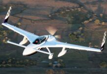
Flutter worries also tend to keep fin aspect ratios down, but with careful design, a relatively high-aspect-ratio, flutter-free vertical fin can be designed. One example of the use of a high-aspect-ratio vertical fin to provide good directional stability is the Questair Venture.
Body Effects
Fuselages are almost always directionally destabilizing. So are engine nacelles and any other body that protrudes ahead of the c.g. of the airplane. In general, the longer the nose of the airplane, the more destabilizing it is. Thus, long-nosed airplanes must have larger vertical fins and/or longer tail arms to achieve the same directional stability as short-nosed airplanes. This is important to the designers of airliners and fighters, which tend to have long noses. Nose effects are particularly troublesome to fighter designers. At the high angles of attack used in air combat maneuvering, not only is the size of the nose important, but also relatively minor changes in nose shape can produce large changes in the high-angle-of attack directional stability of the airplane. On some fighter designs, the unstable yawing moments produced by the nose at high angles of attack can overpower the fin and rudder, leading to loss of control, usually through a rapid yawing motion called “nose slice.”
Yaw Control
In addition to directional stability, the airplane must have acceptable yaw control. While banking is the principal method of inducing a turn, yaw control is needed to coordinate turns and keep the
airplane tracking the runway heading on takeoff and landing. It also allows the pilot to command a steady-state sideslip. Adequate yaw control is vital for safe crosswind takeoffs and landings, and to enable the pilot to control torque and P-factor when the airplane is climbing. It is also crucial when the airplane is flown at or near the stall, as it provides a way of preventing the airplane from entering a spin if it drops a wing.
The rudder provides yaw control. On most airplanes the rudder is a plain-flap control surface that forms the trailing portion of the fin. Deflecting the rudder changes the lift of the fin and produces side force on the tail, producing a yawing moment. The rudder is also one of the primary controls that is used to recover from a spin.
Rudder Effects
If the pilot removes his feet from the rudder pedals, the rudder is free to float with the wind. Allowing the rudder to float decreases the effective area of the fin, because the rudder, which is floating with the wind, is producing less directional stability increment than it would if it were fixed. It is quite possible to produce an airplane that is directionally stable with the rudder fixed, and directionally unstable with the rudder free. This is undesirable, and can be fixed by either aerodynamically balancing the rudder to reduce its floating tendency or by increasing the size of the fixed portion of the vertical fin.
Many WW-I fighters had all-moving vertical fins. Not surprisingly, some of them also had rather exciting directional characteristics, which, in the hands of an expert, made them extremely maneuverable, and in the hands of a less-skilled pilot often proved lethal. All-moving fins are much less common today, and appear on a few high-speed military airplanes such as the SR-71 and the F-117, and a small number of light airplanes such as the Volksplane. While all-moving fins are workable on light airplanes, the designer must be careful to ensure that an all-moving fin has little floating tendency. If the fin has a large tendency to float with the wind, it may, in effect, cease to provide any directional stability at all if the pilot releases the rudder pedals. This could be most unpleasant and should definitely be avoided. Although all-moving fins have been made to work on light airplanes, they offer little advantage, and the potential for serious directional stability problems suggests that they should be avoided in favor of a conventional fin-rudder combination.
Propeller Directional Effects
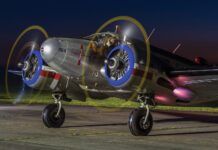
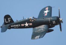
An operating propeller, in addition to producing thrust, produces a side force if the airplane is sideslipping. This effect causes the propeller to act directionally like a small vertical fin. If the airplane is a tractor, this propellers normal force is directionally destabilizing. The airplane will be less stable directionally power on than power off. While this effect is small for typical light airplanes, it can be quite large for long-nose, high-powered airplanes such as WW-II fighters and some of the recently developed turboprop singles. It can also be significant for high-powered twins with long engine nacelles. If the airplane is a pusher, with its propellers behind the c.g., then it will be more directionally stable power on than power off.
The spiraling slipstream of a tractor propeller also causes the well-known P-factor, a yawing moment caused by the swirl component of the propeller
slipstream impinging on the vertical fin. The swirl causes the prop wash to hit the fin at an angle, inducing lift on the fin. This lift causes a yawing moment even when the airplane is flying at zero sideslip. To maintain zero sideslip, coordinated flight, the pilot must deflect
the rudder to counteract the effect of the propeller slipstream and eliminate the P-factor yawing moment.
Next month, we will continue our discussion of lateral/directional characteristics with a look at the roll axis, including the effects of dihedral and sweep.


