Last month we started our discussion of wing sizing with a look at the cruise flight considerations that size the wing. We also learned how to define an optimum wing size for our airplane’s chosen cruise condition. This cruise-optimized wing is primarily valuable as a target to be approached as closely as possible because other considerations very often force the wing to be larger than a cruise-only optimization would make it.
“Pure” Cruise
The only airplanes that can have “pure” cruise wings are cruise missiles because they are launched either with booster rockets or from carrier aircraft, and they are not required to survive their one and only landing. All reusable airplanes must take off and land.
As we have already seen in our earlier discussion of airports, both takeoff and landing distances are strongly affected by both the wing loading (W/S) of the airplane and the maximum lift coefficient (CLmax) the wing can develop. This is because these two parameters determine the minimum speed at which the airplane can take off and approach to land.
It’s important to use the right value for both of these critical parameters in our analyses. Wing loading can be treated as essentially constant for takeoff and landing calculations because, for general aviation airplanes, the airplane might be required to land at or near its maximum gross weight. On the other hand, CLmax is likely to be significantly different for takeoff and landing because of how the high-lift system is configured for each.
Takeoff
On takeoff, the airplane must accelerate from rest to liftoff speed. Liftoff speed must be higher than the 1 G stall speed of the airplane, so the wing can generate enough lift to get the airplane into the air. It also must have enough margin above stall speed, so the airplane can climb away safely.
The ground roll distance it takes to do this is a function of two factors: the liftoff speed and the acceleration the airplane’s engine can generate.
Acceleration is a function of the power-to-weight ratio. The more power the engine generates per pound of airplane, the higher the acceleration will be and the shorter time it will take to accelerate to a given speed. The distance required to get to a given speed at constant acceleration is inversely proportional to the acceleration.
Liftoff speed is a function of wing loading and CLmax. The higher the wing loading, the higher the liftoff speed. CLmax determines how much lift each square foot of wing can generate at a given speed. The higher it is, the lower the airspeed required to generate a given amount of lift. Liftoff speed has a power effect on takeoff roll because the distance required to accelerate to a given speed at constant acceleration is proportional to the target speed squared. This means that, for example, doubling the liftoff speed will increase the ground roll by a factor of 4.
The details of takeoff roll calculation get more complicated when we take into account a host of other factors such as the angle of attack of the airplane on the ground and the way thrust varies with airspeed, runway surface conditions, etc.
A full description of the configuration-specific, accurate-in-detail procedure for analyzing takeoff performance is beyond the scope of what can be covered here. Fortunately, there are simplified parametric approximate methods that are useful for preliminary design and to illustrate the effect of the major parameters on the takeoff performance of the airplane.
One such method is described by Jan Roskam and Edward Lan in their book, Airplane Aerodynamics and Performance. They give the following statistically based equation for calculating takeoff distance of a piston-engine airplane:
Ground roll (Sg) in feet:
Sg = 4.9(TOP23) + 0.009(TOP23)2 (eq. 7.1.1)
Where (TOP23) is the FAR-23 takeoff parameter, which is given by;
(TOP23) = {(W/S)(W/P)}/(σ CLmax)
W = Gross weight in pounds
S = Wing area in square feet
P = Engine rated power in horsepower
σ = Atmospheric density ratio (1.0 at sea level)
Total takeoff distance over a 50-foot obstacle is approximated as 1.66 times the ground roll.
This equation is not precise, but it is accurate enough to do realistic preliminary design calculations and to illustrate the effects of changing parameters on takeoff roll.
These equations were used to generate the curves shown in Figures 1 and 2. All of these numbers are for sea-level standard-day conditions (σ = 1.0).
Figure 1 shows the calculated ground roll for an airplane with a power loading of 15 pounds per horsepower, which is typical of a trainer-class airplane. Performance for two values of CLmax are shown.
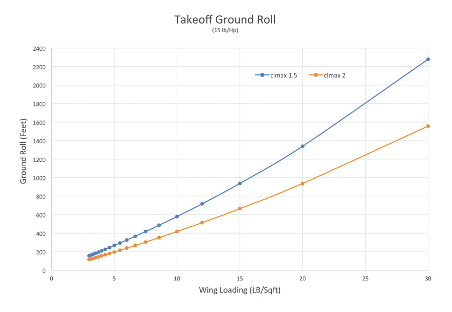
Figure 1: Calculated ground roll for an airplane with a power loading of 15 pounds per horsepower, which is typical of a trainer-class airplane.
The upper curve is for a CLmax of 1.5, which is typical of a general aviation airplane with the flaps retracted. Looking at this curve illustrates the large effect wing loading has on the takeoff ground roll. At a trainer-like wing loading of 10 pounds per square foot, the airplane breaks ground after about 580 feet of ground roll. At 20 pounds per square foot, which is the lower end of wing loading for high-performance singles, the ground roll has grown to 1340 feet. At 30 pounds per square foot, it is up to almost 2300 feet. It’s clear that if the power-to-weight ratio is held constant, the wing size will be strongly driven by the need to keep the takeoff roll down to an acceptable distance.
Wing Loading
Looking at the extreme left end of the curve also gives us some insight into the world of ultralights. Since ultralights are designed with little regard for cruise speed and must meet a 25-knot stall speed requirement under FAR Part 103, they have very low wing loadings. As we can see from Figure 1, an ultralight with a 3-pound-per-square-foot wing loading can get airborne in about 150 feet of ground roll, even with a low power-to-weight ratio and no high-lift devices such as flaps. What we are seeing here is the dramatic effect of slowing liftoff speed and reducing ground roll.
Turning our attention to the lower curve on Figure 1 shows the effect of high-lift systems on takeoff roll. The lower curve is for a CLmax of 2.0. In order to achieve this value, the airplane must take off with its flaps deflected significantly to increase the maximum lift capability of the wing above that of the clean configuration represented by the upper curve. If we first compare the two configurations at the same wing loading, we can see that the roll for the 10-pound-per-square-foot wing loading airplane is reduced from 580 feet to 420 feet. For the higher-performance 20-pound-per-square-foot wing loading airplane, the roll goes down from 1340 feet to 940 feet.
Another way to look at it is to ask what wing loading (and hence wing size) is needed to keep the ground roll below a certain desired distance. If we use our flaps-up airplane as a starting point for W/S=10, we can see that the higher-lift airplane, taking off with flaps deflected, can get that same 580 foot ground roll at a wing loading of about 13 pounds per square foot. This means that the wing can be about 77% of the size of the original wing. If the airplane is intended to fly fast, the original W/S=10 wing will be much larger than the cruise-optimal wing, so the 23% reduction in wing area offered by using flaps for takeoff will move the wing size much closer to the ideal cruise-optimized wing.
One major caution is in order here. This simple parametric equation does not take into account the extra drag produced by the flaps. Even relatively small flap deflections that help reduce takeoff roll make enough drag to significantly hurt rate of climb. The net effect of flaps on obstacle-clearance distance can well turn out to be detrimental unless the airplane has enough power to overcome the extra drag of the flaps.
Power
Figure 2 shows how power affects takeoff roll, and hence wing size. Both curves in Figure 2 are for a clean configuration with a CLmax of 1.5. The upper curve is the same as that in Figure 1 and represents an airplane with a power loading of 15 pounds per horsepower. The lower curve shows the effect of increasing the power of the engine to bring the power loading to 10 pounds per horsepower. The increased power boosts the acceleration of the airplane, so it can get to a higher liftoff speed for a given takeoff roll. If we hold the roll constant, this translates to a higher allowable wing loading. For example, if we again hold the 580-foot roll of our baseline airplane at 10 pounds per square foot W/S and 15 pounds per horsepower power loading, we find that our 10-pound-per-horsepower airplane can now have a wing loading of 15 pounds per square foot.
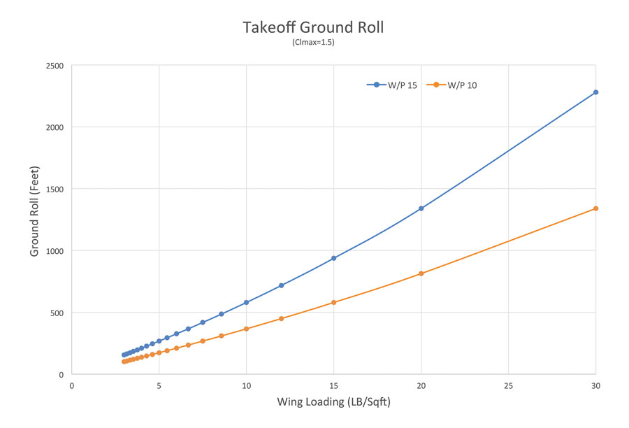
Figure 2: Increased power boosts the acceleration of the airplane, so it can get to a higher liftoff speed for a given takeoff roll.
This illustrates a favorable synergy between requirements for high-performance airplanes. To fly fast, we typically want high power and high wing loading. Adding the power required to drive the airplane to its high cruise speed increases takeoff acceleration enough to enable us to use a higher wing loading and still take off in an acceptable distance. The extra power may be enough to overcome the extra drag caused by taking off with deflected flaps, which would allow the wing loading to increase even more.
Unfortunately for the designer of a high-performance airplane, the synergistic benefits of high power on takeoff performance do nothing to help on landing. Even if the airplane meets takeoff and climb requirements, it must still meet landing distance and stall speed requirements. How these two factors constrain the size of the wing will be our subject for next month.

![]()
Barnaby Wainfan is a principal aerodynamics engineer for Northrop Grumman’s Advanced Design organization. A private pilot with single engine and glider ratings, Barnaby has been involved in the design of unconventional airplanes including canards, joined wings, flying wings and some too strange to fall into any known category.


