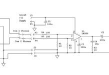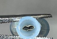
The schematic.
There are those who say that music does not belong on the flight deck, and those who say that flying is miles and miles of nothing but miles and miles. The second bunch (myself included) knows that music sometimes makes it a little easier to pass the time.
However, music these days has taken a far twist from the days when we slapped a Radio Shack car radio into the stack and put up with broadcast FM radio for our source. What with Walkman, iPod, iPhone, and the dozens of other portable music devices that can store literally thousands of songs on a chip the size of a pencil eraser, we have music on command every place we go.
Except the airplane. Why is that? Its because nobody who designed these musical marvels bothered to set a standard for output level or output impedance, and in an effort to get good battery life, some portable music boxes require very efficient headphones that get along on low power output. Unfortunately, the designers of your aircraft audio system could not know in advance which portable audio device you were going to use, and (in general) they designed to the standard line specification with a 600-ohm input and a unity gain amplifier. That is, a volt in to the music input of an audio panel will give a volt out into standard aircraft headphones with an impedance of 150 ohms.
A second small problem is that all portable music players on the market today put out a stereo left and right channel, and many airplanes still use monophonic outputs. Somehow we have to combine left and right channels so that we can hear all of the music.
Fast rewind to 1978. A future college electronics professor, then in his early 20s and working for me, seemed amazed when I told him that there was a mathematically precise reason for each component in a design. Today he regales the students in his classroom (next door to mine) with this story.
The Theory of Everything
Rather than simply present the design of a circuit that will do everything that we ask of it, Im going to take you through the why and the how of each component in the design. That way if you have some-thing else in mind, you can modify my design knowing full well why you chose the value for any single component.
Here we go. V+ can be anything you want below 30 volts and above 5 volts. The output will never go above V+ minus 1 volt and never go lower than zero. The power supply can be fairly noisy if you wish; the LM358 has a typical power supply rejection ratio of 100 dB. This means that 1 volt of noise on the power supply line will produce 10 micro-volts of noise at the output, and I guarantee you cant hear 10 V of noise.
The equation: dB = 20 log V2/V1 and by algebra 10db/20 = V2/V1. In our case, this produces V1/105 = V2; 1 volt/105 = 1 x 10⁻⁵, or 10 microvolts.
What I need to do is drive the (+) non-inverting input of U101A to half of whatever V+ is. This sets the op-amp in the middle of its operating range and allows a full swing of the output up to supply and down to ground. The value of these resistors is a function of C101, which serves two purposes. First, it keeps any noise on the V+ line from getting into the amplifier inputs and acts as a power-on pop filter. What Id like is a slow ramp up of the output to V+/2 in a second or so, which will prevent the op-amp from giving a sharp power-on pop when first turned on.
The value of C101 was chosen as 10 microfarads because it was the smallest electrolytic (polarized) capacitor I had in stock and therefore was small in size. The voltage across the capacitor needs to come to a charge, so we have what is called a time constant where the current through R101 charges C101 slowly. How slowly? τ = R x C, where τ is the time constant, C is the capacitor, and R is simply R101. C101 will charge to 67% of V+/2 in one time constant, which in our case is 100K x 10 microfarads, or 1 second. It will charge to 86% of V+/2 in two time constants (2 seconds) and 95% of V+/2 in three time constants. It will ever so slowly get closer and closer to V+/2 past three time constants, so for all intents and purposes, it will be where it needs to be in 3 seconds. You can come up to speed faster (lower R101 and R102) or slower (raise R101 and R102).
Time to mix the left and right channels together. We can do this at the (-) inverting summing input of U101. The choice of 100 nanofarads (0.1 microfarads) for C102 came from the fact that this is the largest non-polarized capacitor I have in stock. If we want frequency response down to 30 Hz (see the audio response graph), then the impedance (capacitive reactance) of C102 has to be equal to the value of R105 or R106. The formula for capacitive reactance is Xc=1/(2 x π x f x C), so we find that the reactance of a 100-nf capacitor at 30 Hz is 53 kΩ. The closest standard value to this is 56K, so R105 and R106 must be 56K. The summed left and right channels are then output from U101a with no amplification.
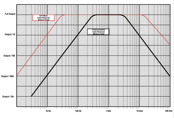
Audio response curves.
R You In?
Some portable music boxes are fussy about what they see on their outputs. Some don’t care if the circuit is high impedance. Some get distorted if they don’t see the impedance they were designed for. If your audio sounds distorted, use these load resistors to set the impedance that the music box wants on its output.
Time to get some useful gain. The gain of U101B is set by the ratio of R107 to R108 and the formula for this gain is G = 1 + (R107/R108). With the values shown, the gain will be 11, so a tenth of a volt at the input will be 1.1 volts at the output. You can play with the values of R107 and R108 to get the gain you desire. However, the capacitive reactance (see paragraph above) needs to be greater than R108 at your low frequency cutoff of 30 Hz. C103 is used to make the upper corner or cutoff frequency 15 kHz, so we find that the reactance of a 10 picofarad capacitor at 15 kHz is 1.06 megohms; 1 MΩ is the closest standard value.
Time for a little electronic cheating. I can guarantee you that the output of U101B is going to be positive all of the time, but I cant guarantee what the audio panel will look like. One little known fact of electrolytic capacitors is that you can hook them back-to-back (or front-to-front, for that matter) and form a non-polarized capacitor with half the value of either capacitor by itself. Im going to assume for the time being that our audio panel designer decided to use a standard line input impedance of 600 ohms, so we need to have a capacitive reactance around this value from C105 and C106. Remembering that the capacitance will be half (5 F) of either capacitor, and we have a low-frequency requirement of 30 Hz, we can calculate the capacitive reactance at 1060Ω. Not exactly equal to the input impedance of the audio panel, so in practice we might want to use the next largest value on the parts shelf of 47 F, which gives us a low frequency corner of 212 Hz. Designers choice. I don’t care much for boomy bass, so Ill let the corner wander up to 60 Hz or so with the pair of 10 F capacitors.
And I’ll bet you thought I did all this stuff by tossing together random values of parts. Nope, each one gets its own individual calculation so that the end product is exactly what I want it to be. Stay tuned. We’ll do some more of this stuff every now and again.’


