A few months ago, we took a look at using LED lights on the wingtips and tail feathers, and said we’d look at power supplies for the wingtips and landing/taxi lights at a later date. This is that later date.
Let’s do a little bit of a recap, and then I have a confession to make. We did a lot of work on the optics of the nav lights, but precious little on the electronics of the lights. I did a lot of handwaving and said that “all will be revealed” at a later time. This is that later time.
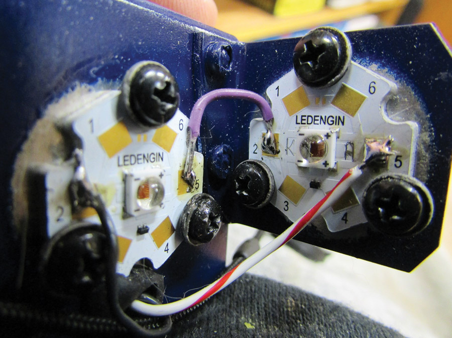
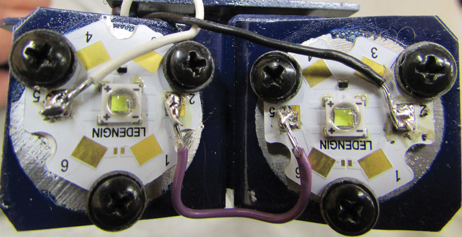
Close-up of the left wing fore and side LEDs. Note that the camera flash “excited” the LEDs in the little square in the center of the round ceramic substrate and caused them to glow slightly red. The LED itself is inside of the little ceramic square marked (+ + and – -). For size, the black screws are #4, and the red/white wire is #24.
So, here we go. The LEDs that I used on the nav lights were individual “dice,” which means that it was just one diode (LED means Light Emitting Diode) on a ceramic PC board. Each wingtip and the tail feathers each had two of these diodes: two red on the port wing, two green on the starboard wing, and two on the tail.
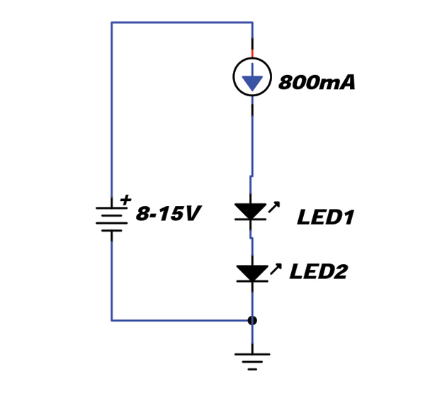
The basic 2-LED power supply with an 800 mA current source. Note that each LED is a 3-watt radiator that corresponds to an approximately 20- to 40-watt incandescent light.
Let’s then just talk about these diodes individually. Whether they be red, green, or white, they mostly all have the same characteristic. They are current-driven devices. Let me say that again for reasons that will be apparent: They are current-driven devices. That is, you don’t feed them with a particular voltage (like you do an incandescent), you feed them with a current—in amperes (or milliamperes), not volts.
Each one of these diodes likes to be fed with a current of about 800 milliamperes (0.8 ampere), and if you measure the voltage across the diode at 800 milliamperes, it is about 3 volts. But feed it a voltage of just 3.2 volts, and it will be conducting a burnout current of well over an ampere. Feed it a voltage of just 2.8 volts, and it will be too dim to see. The problem then resolves itself to finding a current regulator instead of a voltage regulator.
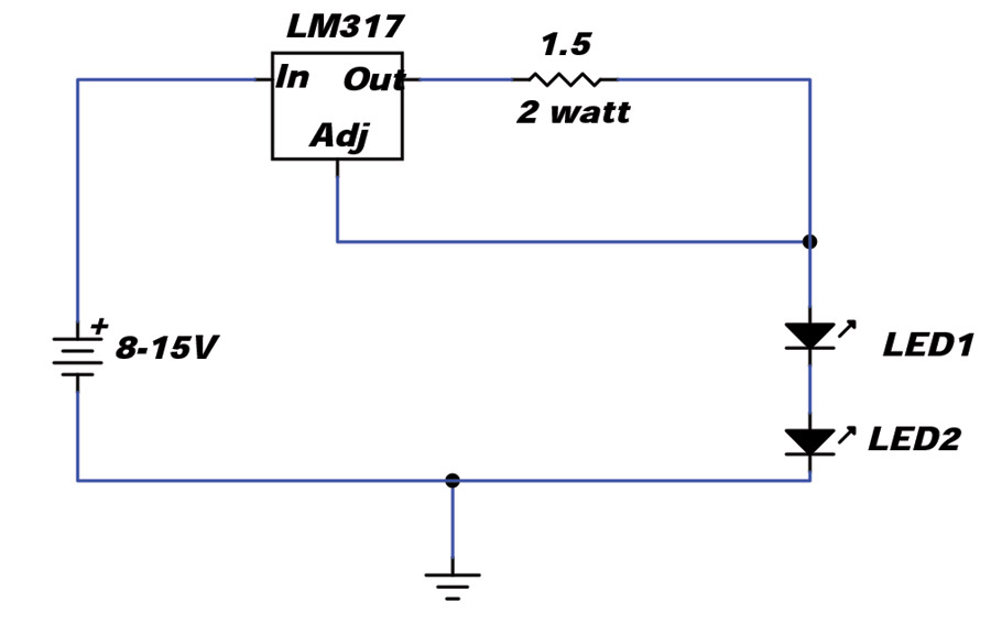
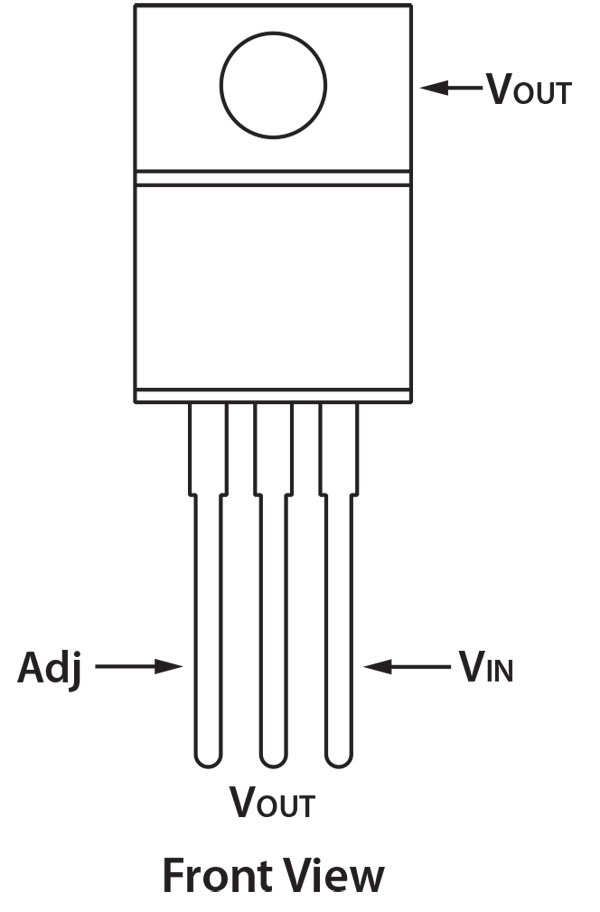
Replacing the 800 mA current source in the previous schematic with a real current source using an LM317 and current setting resistor.
But each of the nav light positions (two wings and a tail) have two diodes each to give us the optical light pattern we need. The clever designer then says, “Aha, I can put the two diodes in series since Ohm told us the current in a series circuit is equal everywhere.”
Now we are getting somewhere. Each of the two-diode pairs needs a regulated current source to feed it a constant 800 milliamps no matter what the aircraft battery voltage is. That poses a problem because you can buy voltage regulators dime-a-dozen; current regulators, not so much. So, using one of the old analog engineer tricks, you turn the voltage regulator into a current regulator. Not so hard as you might imagine.
Remember, Ohm said that a constant voltage with a constant resistance is constant current. The wizened old engineer says, take a voltage regulator and turn it into a current regulator with a known resistance (see the schematic). Knowing that the internal precision regulator keeps the “reference” of the LM317 precisely 1.25 volts below the output voltage, if we put in a resistor of 1.5 ohms (1.5625 to be exact, but we can’t buy that exact a resistor), the output current will be 800 milliamps for input battery bus voltages from 8 to 15 volts.
The resistor is going to have some power considerations. Ohm told us that the power dissipated in a resistor is the current (squared) times the resistance. 800 milliamps squared is 640 milliamps, times a 1.5 ohm resistor, is 960 milliwatts (0.96 watts). Engineering practice is to round the wattage up to the next available level (1 watt) and then double it for reliability. Now we have our current regulated source completely designed. An LM317 voltage regulator combined with a 1.5 ohm 2-watt current regulator resistor gives us exactly what we need.
Almost. We’ve got another consideration to make, and I leave it to you to make the design, as it will be different for each different aircraft. Heat. That nasty stuff that takes battery/alternator energy and wastes it into the atmosphere. Each of those little diode circuit boards will be generating power at the rate of 3 volts times 0.8 of an ampere times 85% loss (15% efficiency turning electrons into light). That means each of the little diode PC boards will have to get rid of 2 watts of heat. The LM317 itself will have to get rid of a maximum of (15 volts of maximum battery volts minus 6 volts of diodes) times 800 milliamps of current or another 7 watts of heat. That’s not a lot of heat (relative to a normal 25 watt incandescent nav light), but you have to deal with it. Aluminum structure is your friend.
Now I have a confession to make. When I did this design for Oshkosh ’15, I did each of the power supplies for the four lights (three nav and the landing light) using a switching power supply that was slightly modified to make it a current supply. I did not do a full EMI (electromagnetic interference) test on it before I took it to the show. Guess what? The little power supplies sang like a bird. That is, I listened when I got home from Oshkosh across the aircraft band, and there were birds and tweets from one end of the band to the other from the switching supply. Not exactly conducive to good communications practices.
Could I clean up the supplies to get rid of the birds? Of course. A little shielding here, a little filtering there, and we are home free. Can I tell you how to do it on an individual basis? Of course not. So we waste a couple of amps of alternator doing it without a switching supply and doing it with a linear power-wasting supply. What did that cost? A couple of amps of excess current times 12 volts is 24 watts. Divided by 746 watts per horsepower means you are losing exactly 0.032 horsepower doing it this “clean” way. Pretty good tradeoff, I say.
But the landing and taxi lights, Jim? Ah, but we’ve come to the end of the page and still no mention of that. Rest assured, in the next couple of months we’ll finish up the LEDing of your airplane.
Until then, stay tuned…

![]()
Jim Weir is the chief avioniker at RST Engineering. He answers avionics questions in the Internet newsgroup www.pilotsofamerica.com-Maintenance. His technical advisor, Cyndi Weir, got her Masters degree in English and Journalism and keeps Jim on the straight and narrow. Check out their web site at www.rst-engr.com/kitplanes for previous articles and supplements.

