 Well, it seems to be the season for alternator problems, as just this week I had to diagnose another interesting one. As with any problem or incident, there is sometimes a chain that leads up to the actual event. One of the practices we have at Base Leg Aviation during the condition inspection is to look at items that may not necessarily require attention immediately, but due to the customer’s annual flying hours, may need to be addressed during the year. Our intent is for our customers to have an uneventful year maintenance-wise, so we will discuss these findings with the customer and together decide on timing. Normally, these are wear items such as tires, brakes or spark plugs. Some can be more invasive, such as magneto SBs, alternators, etc.
This aircraft had over 600 hours on a particular alternator that we’ve noticed has a history of failures between 500–600 hours. The customer uses the airplane regularly and flies IFR as well. I mentioned that he should be prepared for an alternator failure in the coming year. With dual electronic ignitions, both of which require an external power source, a reliable source of power is needed. Since the aircraft had a backup alternator and a backup battery, a decision was made to replace the alternator if/when it failed.
Sure enough, about four months later I received a text from the customer claiming I am the “Zen” mechanic, as his alternator had failed. This owner does a lot of his own maintenance, so changing the alternator was not out of his purview. I did walk him through checking for battery voltage at the field connection on the alternator, and he assured me he measured 12 volts at that point. With 12 volts at the field, and no alternator output with the engine running, it is a pretty good sign that the alternator has failed.
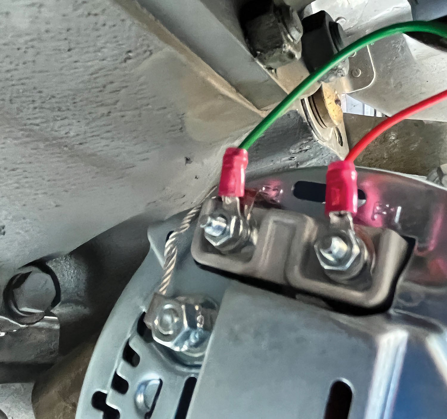
So now the chain continues. Anyone who has changed alternators recently knows that many of the manufacturers have changed the field connector over the years. It’s usually no big deal to cut the wires and splice the new connector into the circuit. Many of the connectors have a wire jumpered across two pins on the connector. The new alternator had two threaded terminals, so it seemed logical for the owner to connect the field wire to both terminals. He called and said the alternator was still not working.
I looked at the texted picture of the new alternator and realized that one of the terminals needed to be tied to ground, not to the field wire. He did that, and it still didn’t work. He also assured me that there was power on the field wire. Hmm…it seemed as though he may have received a bad alternator, so he got another one and it still didn’t work. Now I needed to dig in a little closer, still all remotely, of course.
By looking more closely at the part number on the alternator, it was clear that this one required an external regulator, whereas the original one was internally regulated. I pointed that out and told him which regulator he needed and how to wire it into the aircraft. Guess what? The next text I received was that it still wasn’t working! Now it was time for it to come to the shop and let me figure out what was going on.
Looking for Clues
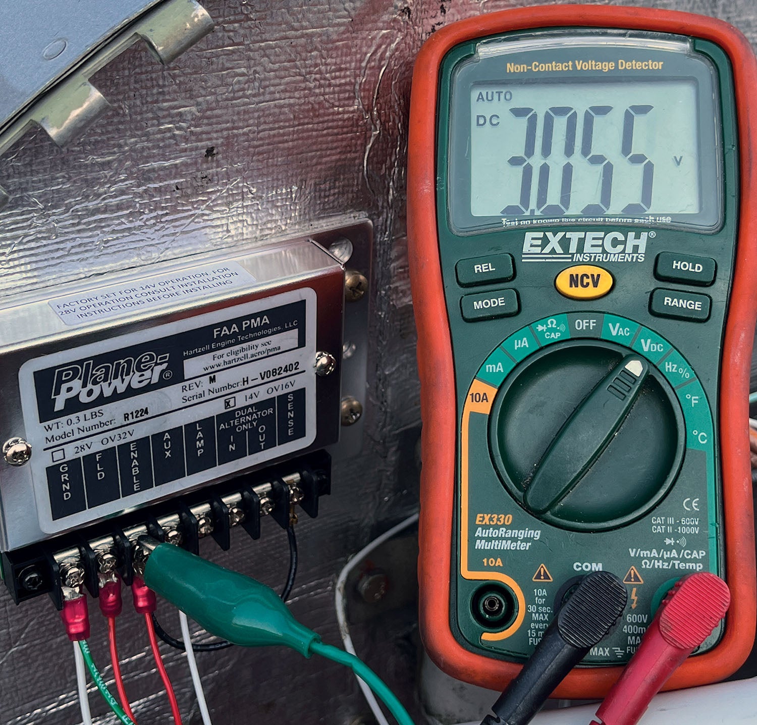
Alternators are very simple in that they need power applied to the field for them to generate power. So, the first thing I always measure is the field wire. In this case, he had installed the regulator right on the firewall, with easy access, and I measured the voltage at the Enable pin, which should be the wire coming from the alternator switch in the cockpit. The meter showed 3.05 volts. Well, it sure isn’t going to work with that voltage level, as normally on the ground you will have somewhere around battery voltage at the field wire, approximately 12 volts. In flight, once the battery is charged, the field voltage will taper off to some lower steady-state voltage. As a matter of fact, what had been bothering me during our back-and-forth troubleshooting was why the alternator had not “run away” prior to the regulator being installed.
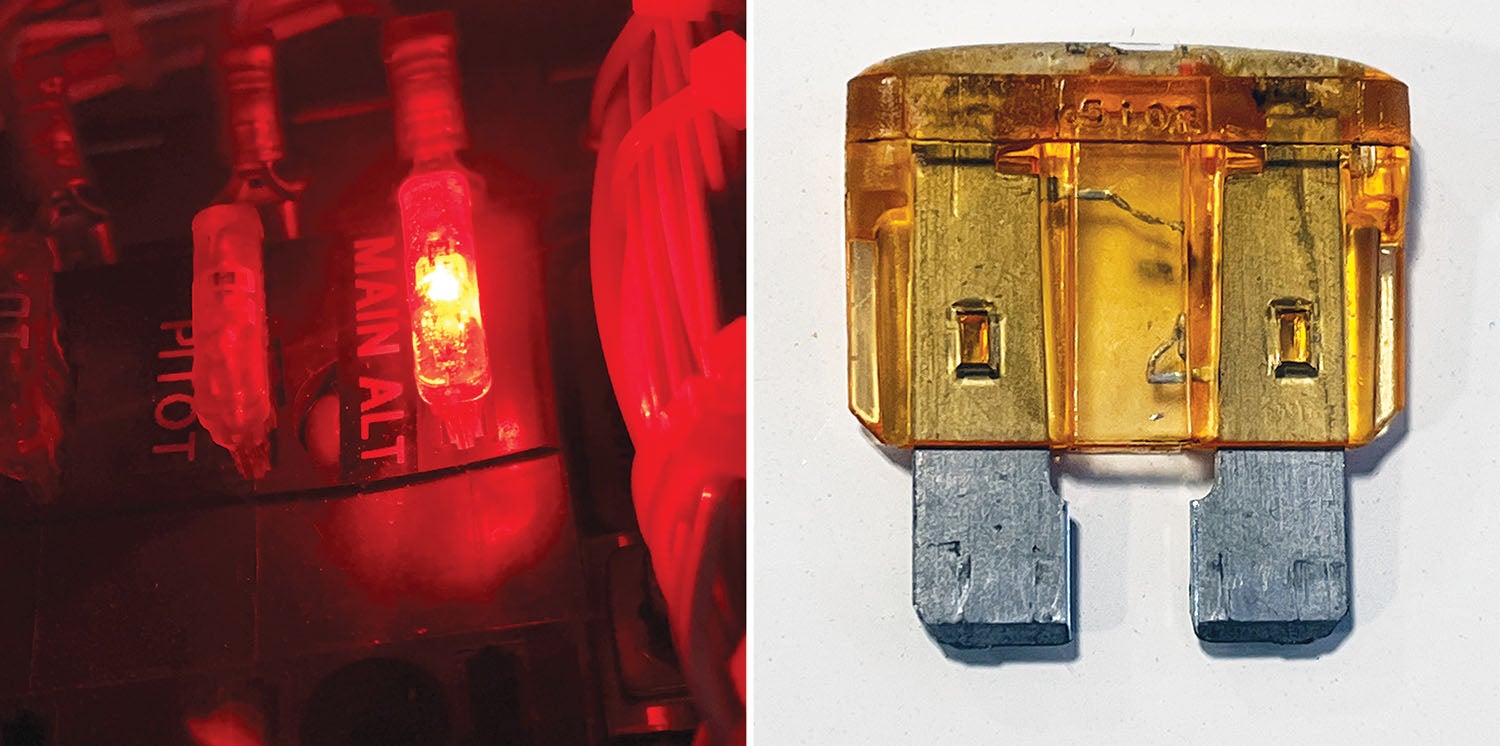
Now I had a real strong inkling as to the source of the problem. I opened the fuse panel and there it was, staring me very brightly in the face and lighting up the whole fuse panel: a blown field fuse, one that has a light in it to show you it’s blown. I replaced the fuse and the alternator proceeded to deliver 60 amps on startup.
Here’s what I think happened, and the owner agrees. The first alternator did fail, as we thought it might. Prior to replacement, he did verify there was 12 volts at the field wire. When the new alternator was installed, erroneously connecting the field wire to both terminals on the new alternator, one of which is a ground, blew the fuse on the field wire. When the new alternator still didn’t work, he claims he checked the field wire voltage and saw something, but he didn’t really notice it was not the bus voltage. Field wire voltage was not checked, even after installation of the external regulator.
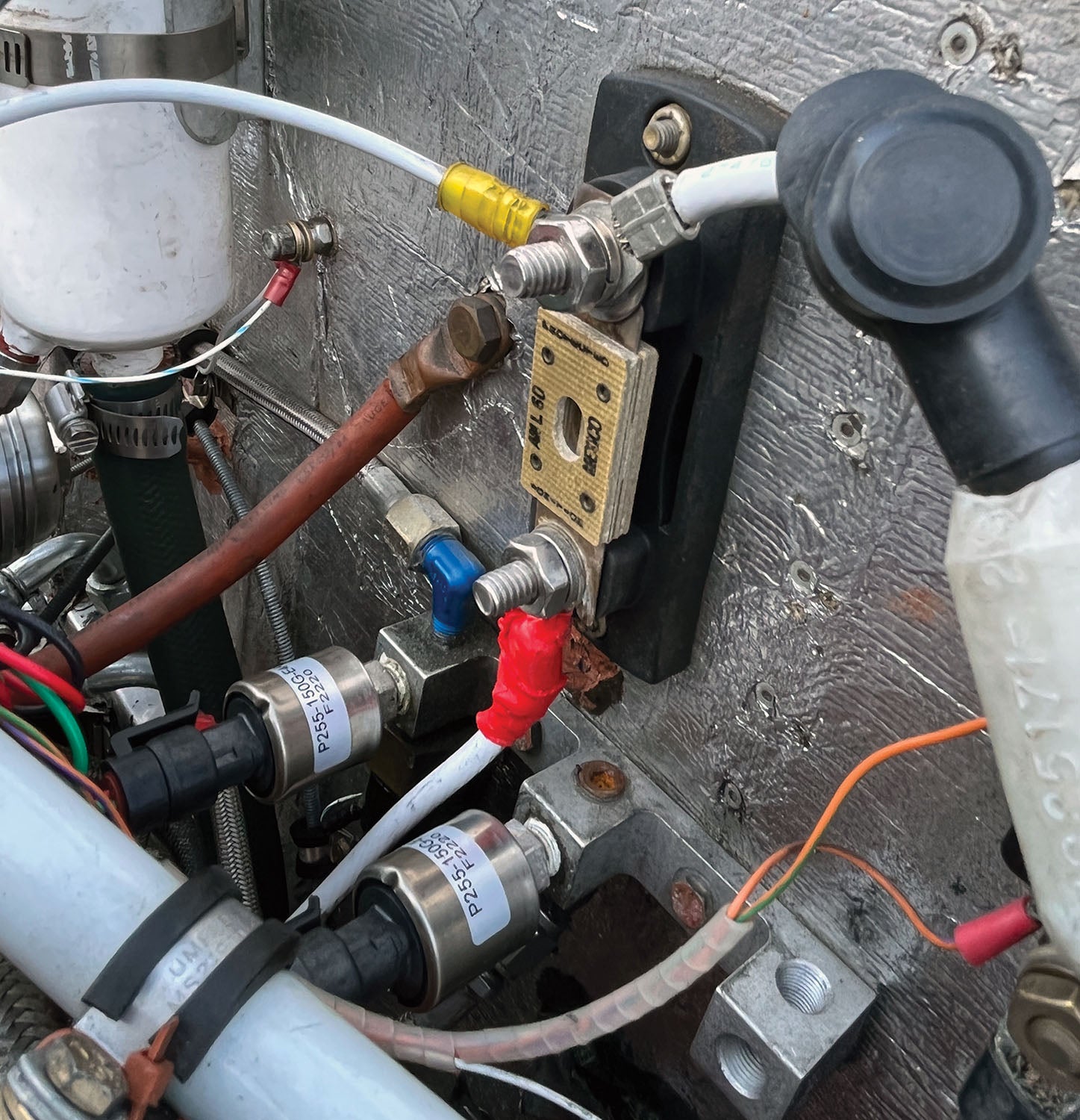
Another tidbit that made the troubleshooting quick and easy for me is that the standby alternator was working. Since they are both electrically connected on the firewall side of the aircraft, I was immediately convinced that everything on the output side of the alternator aft of the firewall was intact.
Some overall lessons here: Perhaps we should more firmly recommend replacement of failure-prone parts while they are in the shop, as certainly it could be less time-consuming for everyone during the year. Second, once parts are replaced, don’t assume that nothing else has changed. When troubleshooting remotely, it is imperative to ask detailed questions. In this case, I should have asked for an actual field voltage value each time. It would have gotten the fun factor back online a lot quicker for this customer.
![[Credit: Lisa Turner]](https://www.kitplanes.com/wp-content/uploads/2026/02/Fuel-Selector.jpg?w=218&h=150&crop=1 "Fuel Follies")


Another quick check to see if you have power to the field is to check the pulley nut on the alternator. It should be magnetized when the alternator and battery switch is on. If it’s not your field circuit is open.
A few years ago my friend’s C-182 battery was low and apparently not sufficiently charging in flight. We recharged the battery a few times on the ground to finally decide that the alternator was at fault. It and its STC was pretty old so we decided to have the alternator overhauled. It was removed, overhauled by a specialty shop at a nearby airport, then it was reinstalled and signed off. The same symptom resurfaced: the meter didn’t show discharge but seemed to stay centered; our 2 to 3 hour cross-countries didn’t seem to charge the battery. The A&P admitted that electrical problems weren’t his long suit but he suggested changing the regulator. He installed the same PlanePower regulator shown above and signed it off. Next flight, same symptom. While I’m definitely not an A&P I’d had vocational training years ago in the Air Force, had subsequently performed on many electrical engineering and manufacturing projects, so I finally decided to look the problem over in detail. It was a mess.
The original alternator STC was available as was the Plane Power regulator STC so I had valid documentation to study. The original installation had a firewall mounted “regulator” but also an interior mounted overvoltage relay. The A&P replaced the firewall mounted unit but left the overvoltage relay remaining somewhere in the circuits. It turns out that in the original installation the regulator doesn’t actually regulate, it just senses voltage error and sends a compensation signal to the overvoltage “relay” which actually controls the alternator’s field coils. Who’d a thunk it. The PlanePower regulator is entirely self contained so the original overvoltage relay was superfluous.
The PlanePower regulator STC and installation instructions covered a number of certificated aircraft and the instructions pertaining to my friend’s 182 were entirely verbal, that is, written out without either a schematic or wiring diagram, just words. I found the STC’s wording so difficult to follow that I could easily see how the installing A&P could have been either misled or even overwhelmed.
I made two pencil copies of the alternator STC’s wiring diagram the second of which I incorporated the wiring changes narrated in the PlanePower STC. I then myself disconnected the wiring made unnecessary by the PlanePower STC, jury rigged the STC alternator and regulator connections, and then we tested the result. Success. By then the original A&P had become unavailable so we found another A&P. When he came to the hangar I told the whole story to him, showed him the original and my revised wiring diagrams, and asked him to rewire the circuits in accordance with my revised drawing and informed by the applicable section of the PlanePower STC. He agreed to, he did so, we tested, it worked, he signed it off, and we’ve had no further alternator problems since over the last three or so years. Let me hasten to add that we NEVER on ANY occasion flew or even taxied the airplane without having had legal A&P inspection and signoff.
My point here is that having an A&P’s blessing may not be enough, that STC (or even OEM/manufacturers) instructions without graphics can be nearly unintelligible thus easily misleading, and so far as I know there’s no requirement to keep detailed (like drawings and schematics) change data beyond the further verbal blather recorded in the aircraft’s respective log books. Having had an extensive manufacturing support and manufacturing quality assurance background invariably using engineering change orders (EOs, ECOs) with other pertinent documentation, I find the currently legal aircraft data and records “system” woefully inadequate. Given the FAA’s glacial pace of change I doubt there can be much relief afforded in my lifetime so I guess we’re left with trying to do the best we can with what we’ve got while scrupulously complying with contemporary requirements and regulations, such as they are. Sigh.
Comments are closed.