At this point in the design process we have determined the wing area. The choice of high- versus low-wing and structural concept of the wing are established. We can now turn our attention to details of the planform.
The most fundamental design decision at this point is the choice of span and aspect ratio. These two parameters are mathematically linked together. Once we have chosen the wing area, the span automatically determines the aspect ratio and vice versa:
AR= b²/S
And conversely
b=sqrt(S*AR)
Where:
b = wingspan
S = wing area
(Note that the use of “b” for span and “S” for area are standard engineering notations in aerodynamics. I don’t know the history of this, but it is the standard you will find in any text or technical report, so it is used here.)
Induced Drag
Induced drag is the portion of the drag of the airplane that is a direct result of the production of lift. It is a function of the span of the wing and the amount of lift the wing is generating. It’s common to think that induced drag is determined by aspect ratio, but this is not the case and that misconception can be a trap for the unwary wing designer.
The actual induced drag of a lifting wing (in pounds, or Newtons depending on unit system) is given by:
Di =L²/(Π q e b²)
Where:
q = dynamic pressure of the airflow
e = span efficiency
Dynamic pressure is proportional to airspeed squared and the density of the air. The reason for the misconception is that the nondimensional induced drag coefficient is a function of aspect ratio:
Cdi = CL²/(Π e AR)
This nondimensional coefficient is what most of us are familiar with. To get actual drag from drag coefficient, we need to multiply the coefficient by the wing area and the dynamic pressure. I will spare you the algebra here, but when all the manipulation is finished, we get the equation for actual drag shown above, in which the span remains but the aspect ratio does not.
The important thing to remember is that for a given lift, density altitude and airspeed, all wings of the same span will generate the same amount of induced drag regardless of wing chord, area or aspect ratio.
More than one designer has made the mistake of making the wing area of an airplane smaller to reduce wetted area and decrease drag and ended up reducing wingspan at the same time, even though the aspect ratio of the new, smaller wing is higher. This usually ends up with an airplane that may be faster at low altitude due to the decrease in wetted area, but climbs poorly and flies slower at cruise altitude due to the increase in induced drag caused by the reduction in wingspan.
One example of this was a NASA-sponsored program to investigate advanced technologies for general aviation. The program started with a Cessna Cardinal and replaced the stock wing with a much smaller wing incorporating sophisticated high-lift devices to keep the stall speed down, an “advanced” airfoil, and spoilers for roll control. The “advanced” wing had just over half the area of the stock wing, and even though its aspect ratio was higher than the stock wing, the actual span was 12% less. In flight test, the “advanced” airplane proved to be inferior overall to the stock airplane with the exception of top speed at near sea level. Its rate of climb was worse, and its cruise performance at any realistic cruise altitude was not much better. The reduction in span canceled out any improvements provided by the advanced technology and reduced wetted area. (See “Flight Test Results for an Advanced Technology Light Airplane,” David L. Kohlman: Journal of Aircraft, Vol. 16, No 4: April 1979.)
The importance of induced drag varies over the flight envelope.
- When the airplane is flying at its best lift-to-drag ratio (L/D), half of the total drag is induced drag.
- At airspeeds faster than the speed for best L/D, the parasite drag is larger than the induced drag.
- At airspeeds lower than that for best L/D, induced drag is larger than parasite drag.
- At the airspeed for minimum power required to fly, which corresponds to best rate of climb for piston-engined airplanes, three-fourths of the total drag of the airplane is induced drag.
These differences affect the span loading that is best for the airplane.
For low-powered airplanes that fly relatively slowly, the need to get acceptable climb performance tends to drive the preferred design toward large span. Motorgliders and ultralights have large spans for their weight in order to be able to climb well with relatively small engines.
It’s interesting to note the difference between these two types as well as the similarity. Part 103 ultralights are limited to a level-flight maximum speed of 55 knots and a stall speed of not greater than 24 knots. This makes parasite drag relatively unimportant and places a premium on low wing loading. Ultralight wings are large, but have aspect ratios similar to heavier light airplanes. They get their low span loading from a combination of light overall weight and the relatively large span that comes from their large wing area.
Motorgliders do not have to meet the same stall speed and maximum speed rules as ultralights. While they need to climb well with low power, they also need to fly efficiently at higher speed and have good enough L/D and sink rate to soar with the motor off.
Accordingly, motorgliders will have higher wing loadings and higher aspect ratios than ultralights. The higher wing loading tends to make the wing smaller, so the aspect ratio must increase to keep the induced drag down to an acceptable level.
Higher-powered airplanes that are intended to cruise quickly cross-county generally have higher wing loadings than slower-flying machines. This tends to make the wing smaller both in area and span. We can compensate for the span decrease somewhat by increasing aspect ratio, but the smaller the wing area, the more structurally challenging (and heavier) the wing gets. Fortunately, the higher power needed for fast cruise where the majority of the drag is parasite drag also gives the airplane more excess power to overcome induced drag in climb.
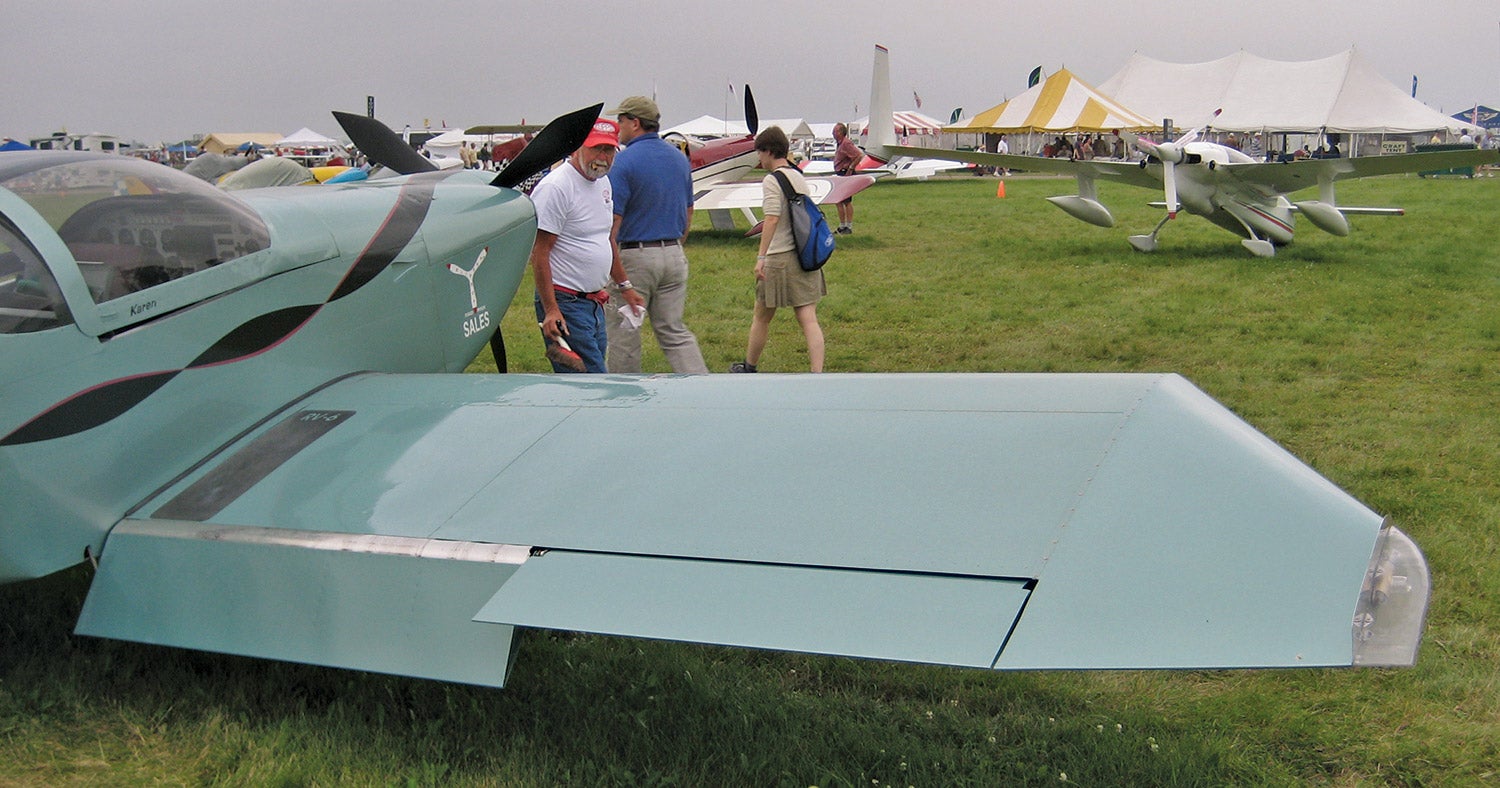
High-altitude cruise tends to favor lower wing loadings and longer spans. There have been several cases in recent memory where wingtip extensions on fast single-engine airplanes actually improved their cruise speed at altitude because the reduction in induced drag caused by the increase in span was larger than the increase in parasite drag caused by the increase in wetted area. The most common example of this is the Glasair line of airplanes that are offered with a standard wing and optional wingtip extensions that double as extra fuel tanks.
(Photo: Dan Nevill from Seattle, WA [CC BY https://creativecommons.org/licenses/by/2.0]).
Weight Trade
Once wing loading has been determined (usually from stall speed or takeoff and landing considerations), the choice of aspect ratio becomes a tradeoff of structural weight against induced drag. Increasing aspect ratio increases span (at constant wing area) but also makes the structure of the wing heavier. The increased structure weight exacts a performance penalty. For each airplane there is a point where the cost (either in material or performance) of increasing aspect ratio and span further outweighs the reduction in induced drag. As we have discussed above, this optimum point varies dramatically depending on the mission and configuration of the airplane.
Non-Aero Considerations
Sometimes the span of the airplane is constrained, not by aerodynamic or performance considerations, but by ground infrastructure. For light airplanes the designer should take into consideration that a lot of standard T-hangars are 38 feet wide. Increasing span beyond about 37 feet may improve performance, but it will also make the airplane more expensive to hangar.
U.S. Air Force fighter designs are constrained in span by the width of the standard hardened shelter on U.S. Air Force bases, and carrier-based Navy airplanes have span constraints imposed by the size of the ship and the need to be able to operate two side-by side catapults simultaneously.
Span issues can also be a problem for large transports. One of the reasons the A-380 did not become more popular is that it did not fit into the taxiway and gate requirements of most airports. While a few major hub airports were willing to build special infrastructure to support the airplane, many other airport operators were not, and the A-380 is thus constrained to serving a relatively small number of airports.
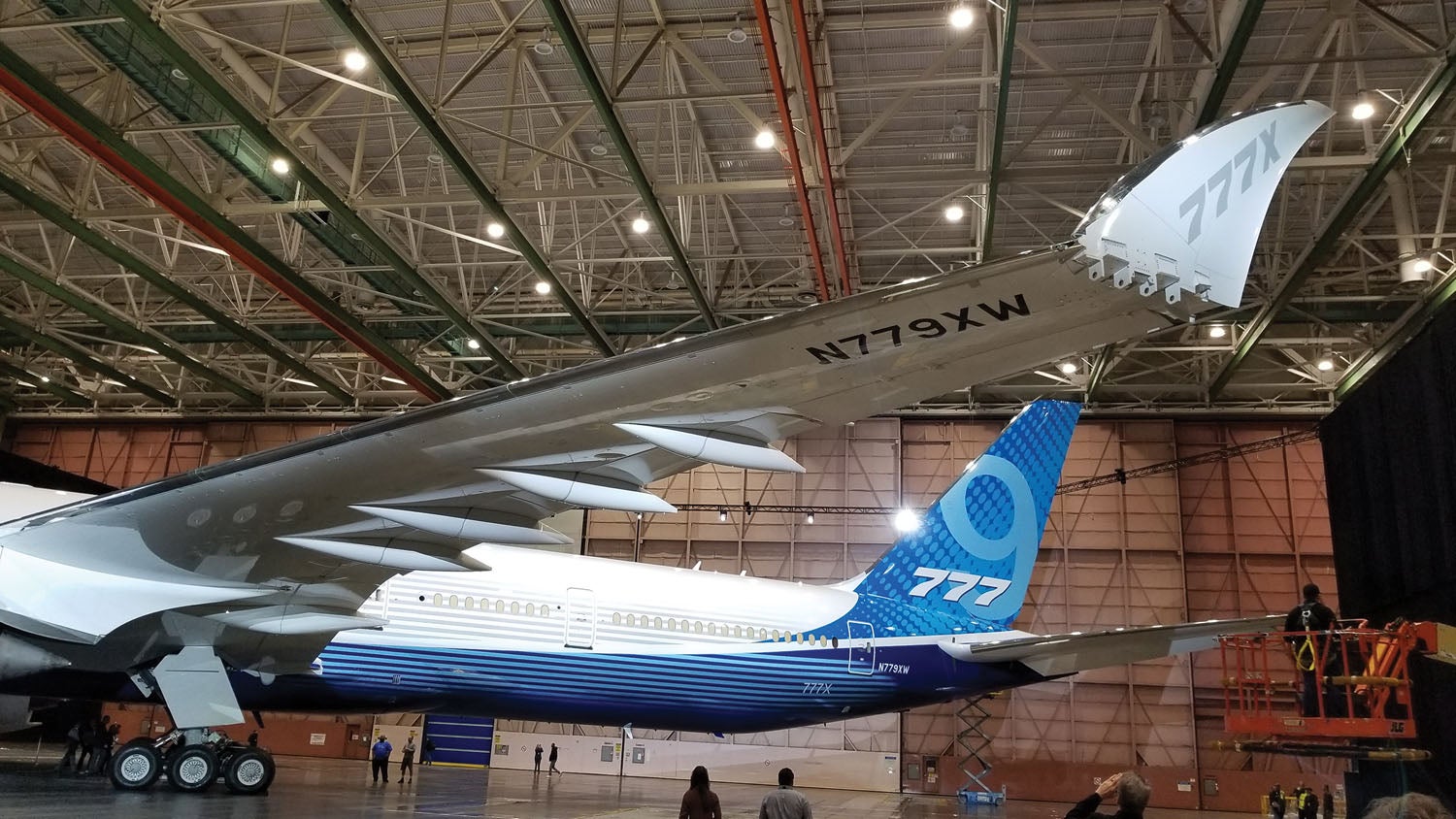
Sometimes, the need for extra span to meet performance requirements is so large that designers must take extraordinary measures to get the needed span and still be able to operate out of existing bases. Boeing recently flew a new version of the 777 (777X) that has folding wingtips. These tips fold up on the ground like the wings of a carrier-based Navy airplane to enable the airplane to use existing gates, but have enough span to fly long range efficiently.


")


Barnaby,
Excellent series of articles on the Design Process. When shall we see an article on propulsion?
Hope you are doing well!
Marty
Wonderful information; simply stated. Nice article that everyone should understand.
How about all the ‘Design Process’ articles compiled in to a book? I’d buy it.
Comments are closed.