
Over the years, we have discussed the “decibel” (dB) at some length (January 2020, November 2019, July 2003 and August 1998). I will thus only repeat the main tenets of the decibel calculation. Please follow along with me through a few elementary calculations.
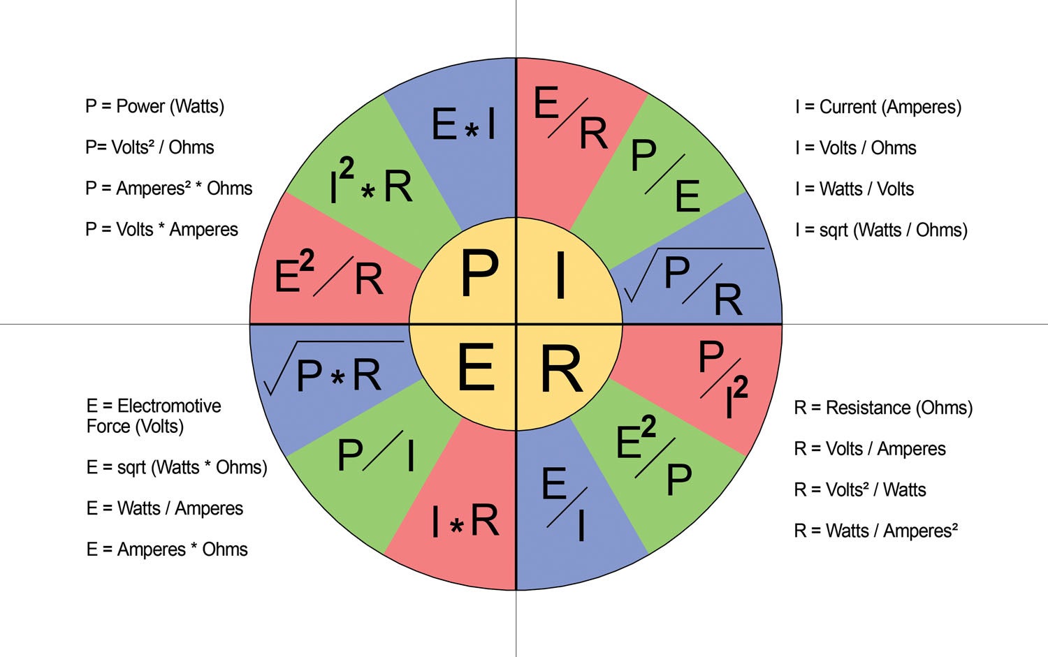
We can use decibel calculations no matter if we are measuring in power or voltage; the calculations and outcome are identical. If dealing in voltage, the equation is that dB = 20 * log (V1/V2). For voltage gains V1 is the output gain and V2 is the input gain. For voltage losses V1 is the output gain and V2 is the input gain. For power, the formula is db = 10 log (P1/P2).
Wait a minute, Weir. The equations will give you different results for voltage and power. In one you are multiplying by 10 and in the other one by 20. Nope, same numbers. Remember, you are dealing with the log function on your calculator, which involved the ratio of either voltage or power to 10x where x is either the voltage or power ratio. And since voltage is equal to (P*R)½ and power is equal to (V²/R), somehow you have to take care of the exponent (1/2 or 2) between these two. That is easily done by multiplying the log by 10 or 20, depending on which way you are going.
At any rate, this column is going to cover “Com Troubleshooting 101,” which was made pointedly obvious to me in a newsgroup where a pilot complained he couldn’t contact approach until 20 miles from the facility. Now, if you presume a 5-watt transmitter in the airplane and a reasonably good receiver at the far end, you can calculate a free-space communications range at something around 2000 miles—which is why we can talk to the astronauts on the Space Station with our little 1-watt handhelds.
Of course, horizon is the limiting factor, and the normal approximation is that horizon (in miles) is equal to (1.2 (h)½) where h is the height above the ground in feet. Let’s presume the pilot was at 1000 feet agl. That makes horizon about 40 miles. But let’s be reasonable and give the pilot the more reasonable altitude of 3000 feet agl. Now horizon stretches out to about 70 miles. And that doesn’t even take into account the knife-edge (“bending”) factor for RF energy at a sharp edge like horizon.
The pilot originally asked the newsgroup if a weak ANR headset battery could cause this. The large number of members of the group that told him he needed a new radio or antenna or coax was startling. They actually convinced the guy that his radio was the problem. And none of them even knew what radio he was using. Amazing. In “the biz” we call this shotgunning a problem: Shoot parts at it until the problem is solved.
Of course, the pilot could have simply been out for a new radio and wanted to convince his wife that the “experts” had troubleshot his problem, and it was an absolute necessity for the safety of her and the kids when flying with the pilot.
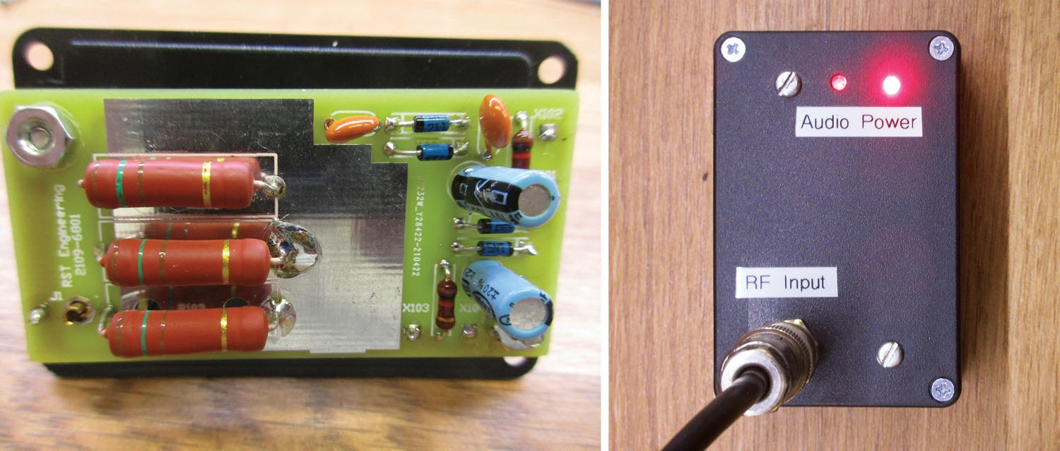
More better, we make a $25 project to test the radio at the input and output of the antenna coax. If so, we can absolve the radio and coax and concentrate on the antenna. Or show definitely that it was either the radio, headset or antenna coax that was the problem. The bottom line: $25 in parts to save a $2000 radio, $500 headset, or replace the coax for $75.
Even more important, we will know what the problem was and that it is fixed.
So here is the fundamental problem that we need to solve. We need to take our radio and give it the “load” it needs. Like testing an engine, we need to give it a club prop on the test stand to load it to the same propeller load that it is going to see in service. (After all, we’d prefer not to see our test stands flying out the shop door.)
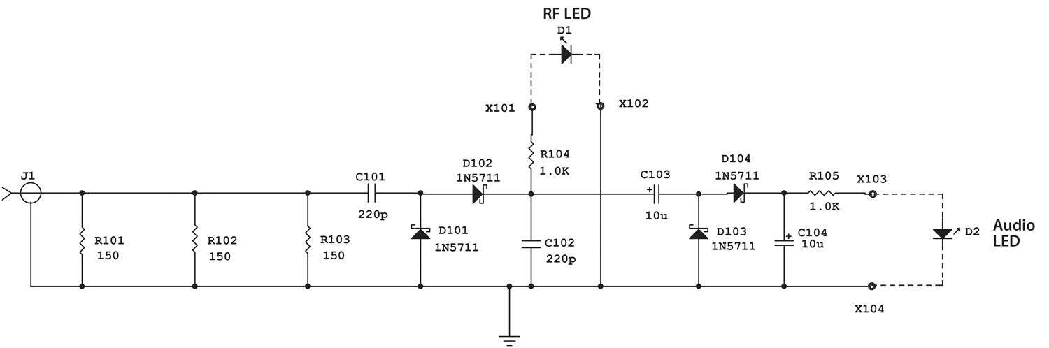
We can do that with what is called a “dummy load.” What’s cheap and available? Metal and carbon film resistors. How much power do we need to handle? The FCC gives the aviation band the latitude for transmitters to put out 25 watts, but most general aviation transmitters put out a maximum of 10 watts (and many put out 5 watts). If we can limit our test to a minute or less, we can use three 3-watt resistors that can handle a temporary overload without a problem. Guess what? Three 150-ohm resistors in parallel gives an equivalent 50-ohm load. Nine watts of resistors for a short time can certainly handle a 10-watt transmitter.
Yeah, but so what (or watt)? How does that let me test anything? Well, that power across that resistance is going to generate a voltage, yes? (See paragraph 3.) And if I take that RF voltage and convert it to a DC voltage with RF diodes and use that DC voltage to turn on an LED, I can certainly say that the transceiver is putting out power.
Of course, it doesn’t tell me how much power unless I put a DC voltmeter on it and calibrate it for power output, but it is a go/no-go quick-and-dirty indicator of power.
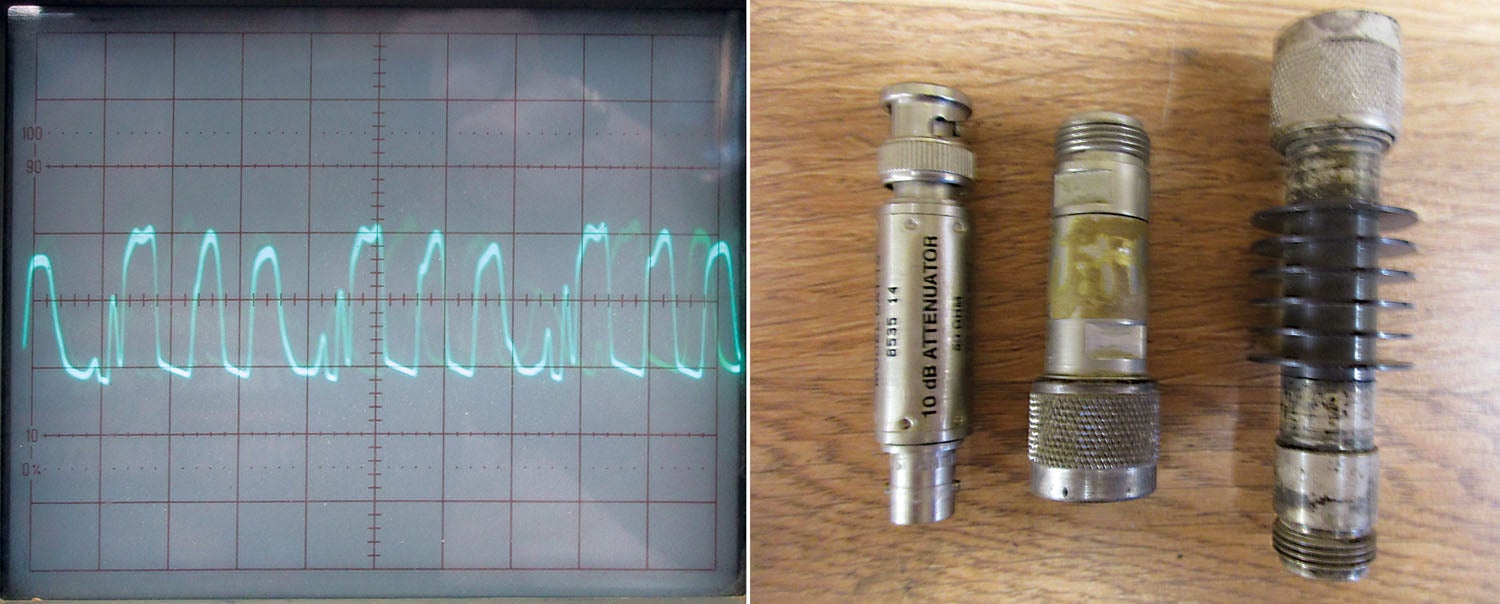
If I then use a capacitor to couple the audio part of that power and convert the audio voltage to DC, I can see if my headset microphone is actually modulating (putting the voice) onto the RF output power.
So here’s the procedure: Put the test box directly on the output connector of the transmitter. Push the PTT switch. Is the RF lamp lit? If so, your radio is OK. Talk into the headset. Is the Audio lamp lit in time with the audio? If so, your headset is OK.
Take the antenna coax and put it back onto the output connector of the transmitter. Put the test box at the antenna coax at the antenna end. Repeat the above test. If it doesn’t work the same, the coax is bad. Replace the coax.
If it works the same, your antenna or installation needs some work (like with the VSWR bridge we designed in last month’s column, “A Match Made in VSWR Heaven”).
Look at your antenna installation. The antenna itself needs to be mechanically and electrically connected to the ground plane of a metal airplane. The mounting hardware needs to have serious lock washers on the metal side of the airframe to dig into the aluminum. In 60 years in this business, I don’t think I’ve seen two defective antennas but dozens of problem installations.
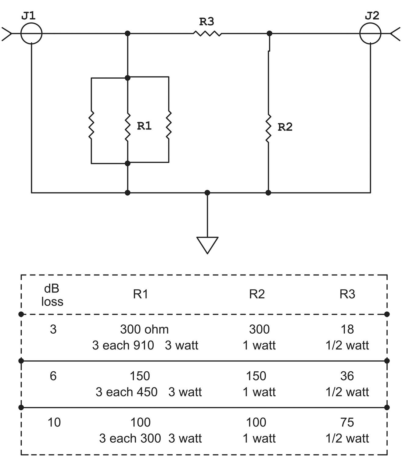
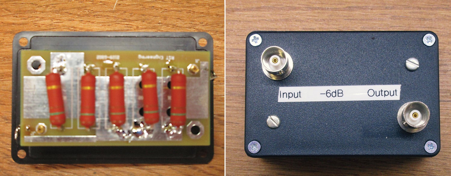
Every now and again, we need to knock the power of a transmitter down to do some other measurements. Here is a cheap way of doing that. These are called “pi” pads because they resemble the Greek letter π. They match both the input and the output to 50 ohms, but I admonish you not to swap the inputs and the outputs as they have to dissipate a lot more power at the input. Three dB cuts the power in half. Six dB cuts the power in a quarter. Ten dB cuts the power down to 10%.
The snow is off the ground. The apples are in pink-bud. Hopefully, HOG will be back with us shortly.
Until then…Stay tuned…
Photos: Jim and Cyndi Weir.


s")


