Here we go with what I promised you last month. This may be the simplest—and yet the most complex—discussion of what it means to be off the commercial power grid and to electrify the solar hangar.

Way back in the early part of the 20th century, we found that this newfangled vacuum tube stuff wasn’t so easy to design if the power line voltage coming into the house (or lab) varied all over the map. And back in the days before we knew that we were going to do more than just light incandescent lights with this power, we couldn’t have cared less if the voltage varied a few dozen volts up or down from the design center of 117 volts alternating current. Or that the frequency varied a few hertz (back then we called it cycles per second, CPS for short) from the design center 60 Hz. No big deal.
That was, until we started designing radios. It turns out (with both vacuum tubes and transistors) that the internal workings of these devices varied with supply voltage. You tune the radio to one frequency today, and if the voltage isn’t the same tomorrow then you will be off-frequency with your tuning. Generally, this is unacceptable. Also unacceptable is setting your volume control to a pleasant listening level today and getting either a whisper or thunder the next day.
In the vacuum tube days, regulating voltage meant adding a couple more tubes, and those hot, power-hungry monsters ate up power and real estate on the chassis just to provide the most primitive voltage regulation. However, along came transistors, thousands of which can dance on the head of a pin, and you can have some pretty decent regulation for not much power and even less real estate.
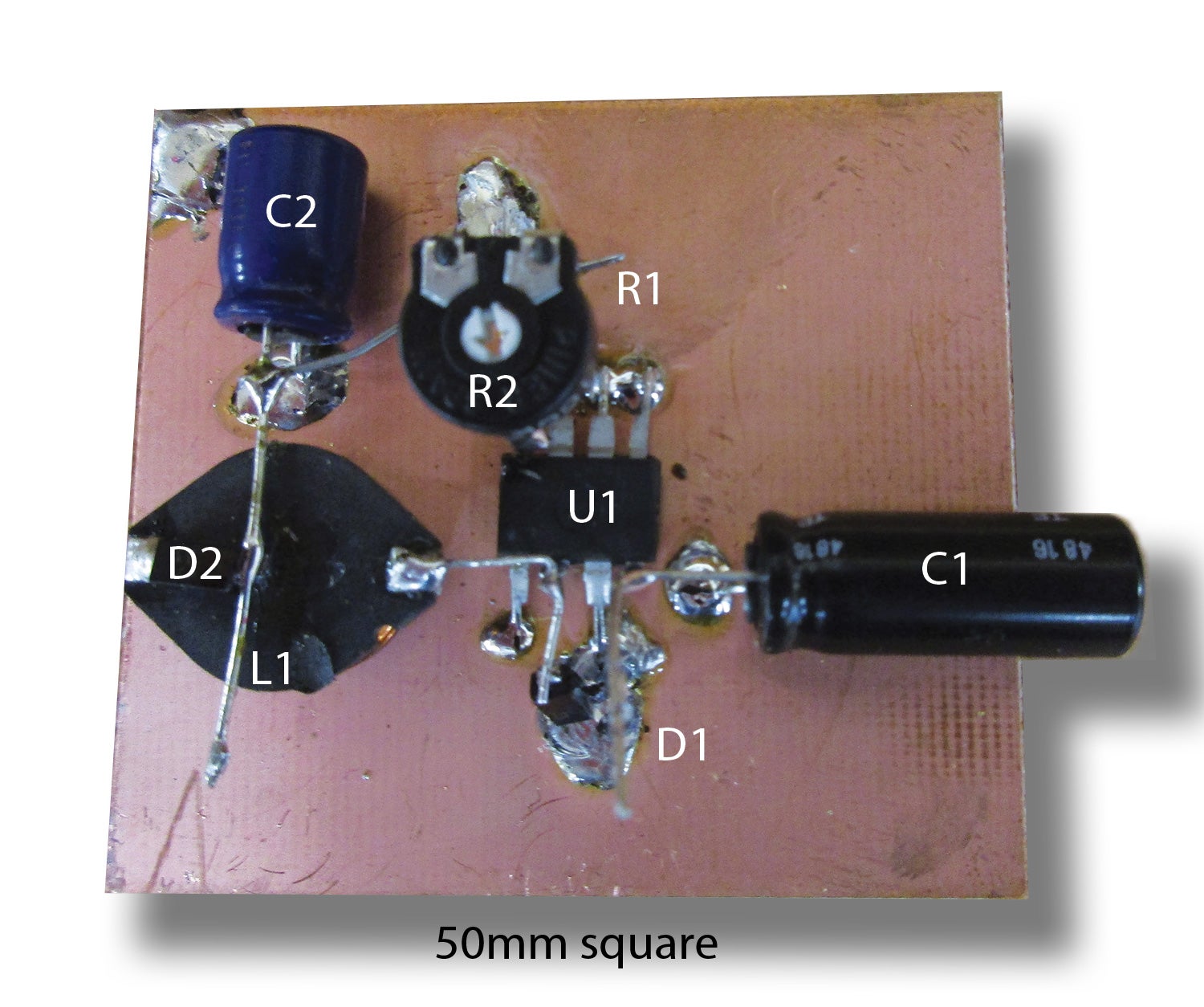
The batteries in an off-grid system tend to want to have a rather well regulated charging voltage, but the solar cells that provide that voltage run wildly up and down. Both of the solar cells shown in the photo go from a few millivolts (thousandths of a volt) on a dark night to well in excess of 25 volts in bright daylight. Somehow we need to run that voltage down to somewhere just a bit below 14 volts to keep our batteries charged up for full-power hangar operations.
In the world of solid-state (i.e., transistors versus vacuum tubes), the linear regulator was king from the 1950s until well into our new millennium. A well-designed linear regulator could keep this wide swing of input voltages mentioned above to a few millivolts at the regulated output.
The problem with linear regulation is that you throw away the power you don’t need in the form of heat. That is, you spend real dollars getting a decent source of power (be it from the wall plug or solar cells) and wind up wasting a lot of that power heating up the environment during the regulation process.
In roughly 2005, the switching regulator started throwing its weight around. The early ones were noisy, twitchy and not very well behaved. If you looked at them cross-eyed, they tended to disappear in a puff of magic smoke. They also tended to radiate noise from the audio range well into the VHF (com and nav radio) bands, and they got a well-deserved reputation for being fragile and noisy.
But they have a saving grace. They have an efficiency that can be 95+%. They throw away very little power doing their job. So National Semiconductor, Motorola, Texas Instruments (and a dozen smaller players) worked their magical efforts into taming this savage beast. Indeed, today they can be made small, rugged, inexpensive, quiet…and all of the above in one package.
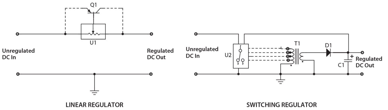
Here’s the deal: Linear regulators simply put a controllable resistive element between input and output and dissipate the unwanted power in the resistor. Note that the original name for the transistor was transfer-resistor, so the resistive element of the solid-state regulator IC was commonly a transistor. If you were using a lot of power that needed regulation, you needed a heat sink on the “transfer resistor” to get rid of the heat.
Switching regulators, on the other hand, depend on the fact that inductors (coils) store energy in a magnetic field and capacitors store energy in an electric field. Match these two fields and feed them with a series of digital pulses that are either full-on or full-off so that no power is wasted and all of the power (power is the product of voltage times current) from the input is used, and you can store that power in a capacitor and inductor respectively. It’s almost like the switching circuit inside the IC can work into a pair of coupled inductors (common name “transformer”) to store that energy and release it into the regulator circuit to keep the voltage and current constant into the load. It’s the best of both worlds at the cost of a coil of wire and a capacitor.
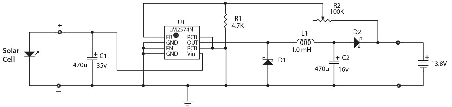
Let’s start off simple. I want to take that little red 1.5-watt solar cell (Harbor Freight #62449 or #64251, $15) and dump every bit of charge that I can into my hangar radio 12-volt battery power supply. That battery likes a charge of 13.8 volts to top it up. If we do the math, and remembering that power (watts) is the product of voltage times current, we can say that current is equal to watts divided by voltage. We know watts (1.5) and voltage (13.8), so we can say that this device should be able to pump about 0.107 amps (107 milliamps) into the battery, which should be just fine if we only want to use that radio in the hangar on weekends. This is a very inexpensive way to get our feet wet into solar energy.
 But I’d like to be able to use our design to put up to half an amp (500 mA) into the battery so we can use a 5- to 8-watt panel for a bit more money later on. I’ll do the design with a switching regulator that can provide up to half an amp. We’ll get into multi-amp systems as we go along, but to get our feet wet into the process, this is a nice way to ease into the game. And, if we make a mistake, it doesn’t break the family bank account to do it over.
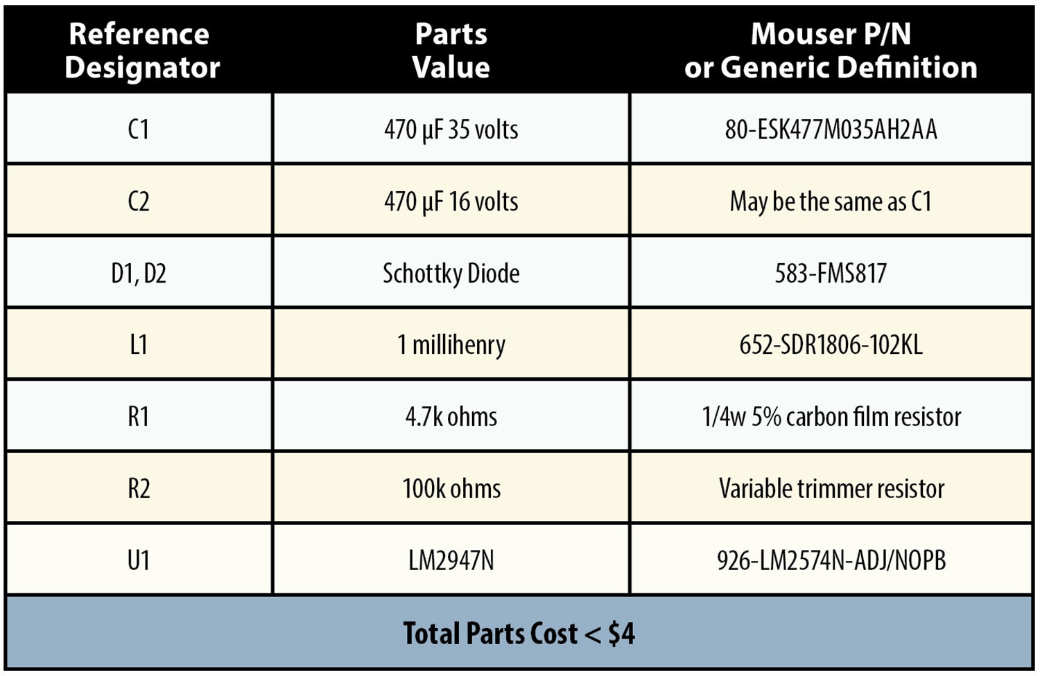
I’m going to give you the design and use Mouser Electronics parts numbers. You can go to Mouser, get the specifications, and use any parts source you wish (Digi-Key etc.) as your supplier.
See you next month with a lot more goodies that you can make for your homebuilt airplane. Until then… Stay tuned…


