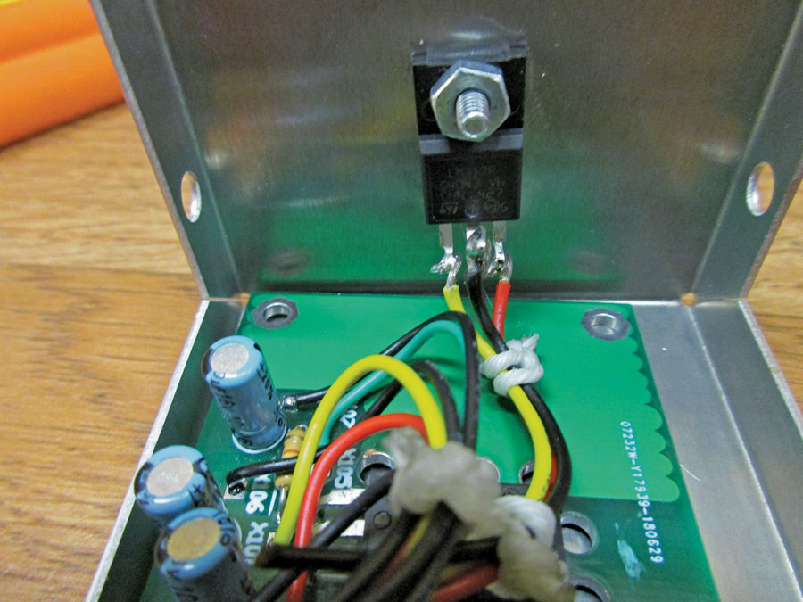
The regulator IC mounted to the chassis box of the circuit board. This makes a wonderful heat sink, especially as the chassis box will probably be bolted to a large metal part of the airplane structure.
After teaching this stuff for so long,1 you’d think I wouldn’t get nipped in the behind so often. It just goes to show that a necessary invention is sometimes a mother.
I showed you several times over the last couple of dozen sessions that an integrated circuit (IC) can be used as a variable voltage regulator. They are simple, easy to use, and bulletproof. Almost. This month’s column is going to show how to make a voltage converter to most any constant voltage that you want, say 5 volts to charge your cell phone, 9 volts to run a battery-powered radio, 3 volts to replace two AA cells in your handheld…indeed nearly any low voltage from a plain old aviation 12- to 14-volt battery bus.
So, to prove to myself that the voltage regulator will be stable and within current and temperature limits, I chose a test load of a regular old automotive incandescent lamp. You remember those—the ones that glow in the dark and provide cockpit heat in the wintertime? Then I was going to overload the regulator and try to give you some trickery to get more current out of the regulator by keeping its temperature within published limits (and a generous safety factor to boot). And then the trickery started. Not on my part, but from the voltage regulator IC.
Out of Control
The IC I chose was a 3-amp device, and by keeping the current to 1 or 2 amps or so, I figured that it should be really child’s play to keep current and temperature controllable. As it turns out, the child was a roaring monster.
Here is what I failed to consider. Every semester for the last umpteen years, I’ve been teaching my students that tungsten is a really strange animal in that it has what is called a “positive temperature coefficient of resistance.” In plain language, that means as the temperature of tungsten goes up, its resistance goes up right along with it. Concomitantly, as the temperature goes down, the resistance goes down. In general for incandescent lights with a filament temperature of 2500 C (4500 F), the ratio of incandescent resistance to room temperature resistance is on the order of 10:1. That is, if a 12-volt 2-amp bulb has an incandescent resistance of 6 ohms (12/2=6), then at room temperature it will have something like 0.6 ohms of resistance.
So? Big deal? Yes, big deal. All of today’s voltage regulator ICs have what is called a “bandgap reference,” which means that we are using the natural makeup of the silicon atom as an ultra-stable voltage reference that varies little over temperature. This bandgap can be diddled a little one way or the other, but the most stable and natural voltage is 1.2 volts. And this is the lowest voltage that the regulator can be adjusted to. Both incandescent and LED lamps will be stone dead of light at this low of a voltage.
So, fat dumb and happy, I adjusted the voltage regulator and bulb to what my temperature meter showed to be the maximum temperature of my regulator (about 9 volts with the 12-volt incandescent bulb at about half brightness) and watched the temperature climb. When it got outside my safe zone, instead of turning off the battery supply as I normally do, I got lazy and just turned the regulator down to “zero.” However, as we said above, this is not true zero, but about 1.2 volts. Now the task was to figure out how to keep the temperature of the IC at something reasonable at maximum power dissipation of the IC at 9 volts.
At 9 volts maximum temperature and with the bulb at incandescence, I calculated that the regulator IC was dissipating about 4 watts, which may not seem like a lot of power to you, but to something a little less than half a postage stamp in size is a fair amount of power. When I shut it down, it was at about spit-sizzle2 hot (100 C, 212 F) and climbing. Just to prove to myself that it was at maximum, I ran the voltage down, down, and the temperature started dropping. When I got down to where the filament was just glowing cherry red, I turned the “brightness” control all the way down to “zero.”
As the filament began to rapidly cool off, the IC temperature started a rapid climb—more rapid than my fingers could accommodate. When the temperature passed the 125 C (250 F) mark, the internal temperature limit switch of the IC took over and saved the IC. But what would have caused the temperature to take such a dramatic and instantaneous rise with the bulb completely unlit?
I wish I had learned how to smoke a pipe. Isn’t that the way most of those 1950s science fiction movie problems were solved? The engineer sat back in his chair, smoked a pipe, and came up with a clever fix to a difficult problem.
Me? I bash my head on the brick wall until it hurts too much, then go back and fight it out on the test bench. About an hour later, it hit me. The output voltage wasn’t zero. It was 1.2 volts. The filament had cooled off until the resistance was the aforementioned 0.6 ohms. The current by Ohm’s law was 2 amps, not zero. The voltage across the IC was (12 – 1.2 = 10.8 volts). The power being dissipated in the IC was theoretically over 20 watts. Measuring the actual current showed that the regulator was supplying about 0.7 amps, for an actual dissipation of nearly 8 watts. No wonder it was getting hot at twice the 4-watt dissipation of the presumed hot spot, 9 volts.
Now, with LEDs that’s not going to be a problem. LEDs don’t have a gigantic coefficient of temperature like an incandescent, so that problem would never have shown up had I used an LED load. But 10-watt LEDs are (a) hard to come by and (b) bright enough to blind you in a dark aircraft. So, with incandescent bulbs on our adjustable voltage regulator, if I’m using it with incandescent bulbs (right out of the 1920s), then I’d best figure a way to get a lot of heat out of it.

Cut off pins 1 and 3 at half length and bend them up into a tiny hook at their ends. Leave pin 2 (the center pin) full length, and bend it up at right angles to the IC with a tiny hook at the end. Connect moderately heavy wires (#20) to these three pins by tinning the wires (use a thin coat of solder) and then bending them into a hook. Then hook the wire with the hook of the pin, crimp both together, and solder.
Reducing Volts and Heat
So now we come down to the two tasks I wanted to cover when I started this article…how to make a voltage converter for any voltage less than battery bus voltage, and how to get rid of heat in the IC when you start to draw significant current.
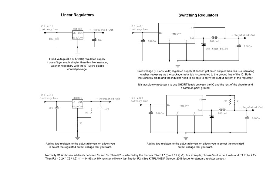
Voltage converter first: You have two options, a linear regulator and a switching regulator. The tradeoffs are that a linear regulator only needs the regulator, two resistors, and two capacitors, but the efficiency is horrible. With a 5-volt 1-amp regulator at full output, the load (the lights, the cell phone) is using 5 watts, but the IC is dissipating 7 watts for an efficiency of 40%. The same situation, same load, same current with a switching regulator, the efficiency will be between 85 and 90%. The tradeoff is that the switcher needs an inductor and a high-efficiency Schottky diode in addition to the resistors and capacitors of the linear regulator.
If you can pick a standard voltage to use (3.3 volts or 5 volts), you can eliminate the two resistors and just buy the standard voltage version of the regulator. For any other voltage, you buy the adjustable version and set the output voltage as the ratio of the resistors.
As for getting rid of the heat without going to a fancy store-bought heat sink, you can simply use the chassis box that you will enclose the regulator in, and wire the regulator to the PC board with short insulated wires. Zero cost and an excellent large-area heat sink.
As I write this, we are loading up and getting ready to depart for Oshkosh. It is going to be a long hot trip across the country, and the temperature is going to be mostly miserable. Looking at front windshield sunshades, I find them anywhere from about $300 (!) down to ten bucks or so. Most of them are the fold-up difficult-to-easily-put-away variety, and a lot of them are absorptive furnaces, not insulators. I’ll do you one for less than $2 that will fit in an old sock, reflect 90+% of the heat, and last for over a dozen years. And maybe some other stuff from Oshkosh for your winter musings. Until then…Stay tuned…

![]()
Jim Weir is the chief avioniker at RST Engineering. He answers avionics questions in the Internet newsgroup www.pilotsofamerica.com-Maintenance. His technical advisor, Cyndi Weir, got her Masters degree in English and Journalism and keeps Jim on the straight and narrow. Check out their web site at www.rst-engr.com/kitplanes for previous articles and supplements.

