I love to look at the beautiful work and magnificent instrument panels that our KITPLANES® readers show us in these pages. But I also know that for each show-quality aircraft, there are some that are…utilitarian. In particular, I’m sure that there are thousands flying around with the most spartan of instrumentation. I’ve seen my fair share of them that a lot of our colleagues are flying with a com radio, a GPS and a big smile on their faces.
I’ve been asked more than once if that “aux audio” input on most com radios couldn’t be used for such things as iPhone/iPad recorded music, Android headphone audio and other non-aviation audio sources. The answer, of course, is that it is quite easy to do any or all of these…mostly at the same time. The circuit involved is called a “summer,” or more properly, a “summing junction.” Let’s do the easy stuff first.
Any electronic device used for communications, be it audio, RF, microwave, GPS, transponder or ADS-B, has what is called a “characteristic impedance.” For RF (including nav, com, GPS, transponders and ADS-B) this is 50 ohms (Ω). (To see the history of 50Ω, read my September 2018 column regarding British squirrels.) For aircraft “audio inputs” such as you may find on your com radio or audio panel, it is universally 600Ω and most generally 1 volt for full output.
For most “civilian” audio devices (iPad, iPhone, MP-3 player, etc.), it is all over the map. Some are designed to drive 8Ω headphones, some 32Ω headphones and some 150Ω headphones. Some off-brands are in their own world, and you are on your own to figure out what impedance they like to drive. However, for the most part we can make the load so high that it will take care of 99.9% of all cases.
Let’s take the simplest case of a monophonic (single) audio output that we want to listen to on the “aux audio input” of our com radio or simple audio panel. Refer to Figure 1.
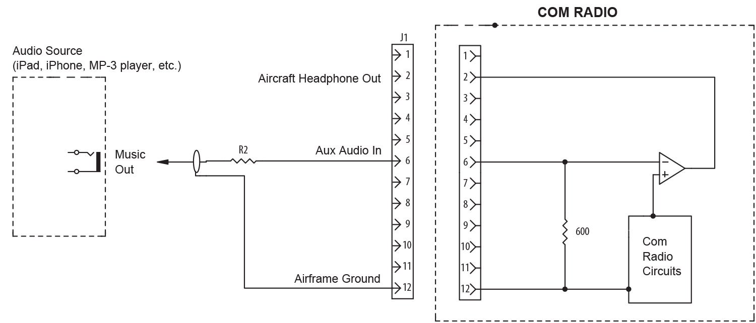
Internal to the com radio, the “aux audio input” is shown with a 600-ohm internal matching resistor. There are a dozen ways to do this, but for our purposes it can be represented by a “real” resistor of 600 ohms. Almost all aux audio inputs I’ve ever come across are rated for 1-volt input for full headphone output. And, almost universally, the internal power supply of the radio means that the output will go from zero (ground) to +10 volts peak. That means that we would like to drop the input down to no more than ground to 1-volt peak, or a 10:1 volt reduction.
Now, being somewhat of a cautious engineer, I like to presume (not ASS-u-me, which is totally different) that most modern entertainment devices use the USB 5-volt bus to charge the device, which means that the “music box” (iPad, iPhone, MP-3 player, etc.) itself is not capable of putting out more than 5 volts peak at the audio jack. If we once again say to ourselves that we really want some sort of margin for low battery and the like, we might say that the maximum signal we want to set the volume control of the music box for is 3 volts. Now the problem simply resolves itself to taking a 3-volt signal down to 1 volt.
So, to calculate the value of R2 in Figure 1, we say to ourselves that if we want to drop a 3-volt signal down to 1 volt, that means we want to drop 2 volts across R2 so that there is 1 volt left across the 600-ohm aux audio input of the radio. Ohm (Georg Simon, late of the University of Munich) told us that voltage divides proportionally, so if we make R2 1200Ω, we will get what we asked for.
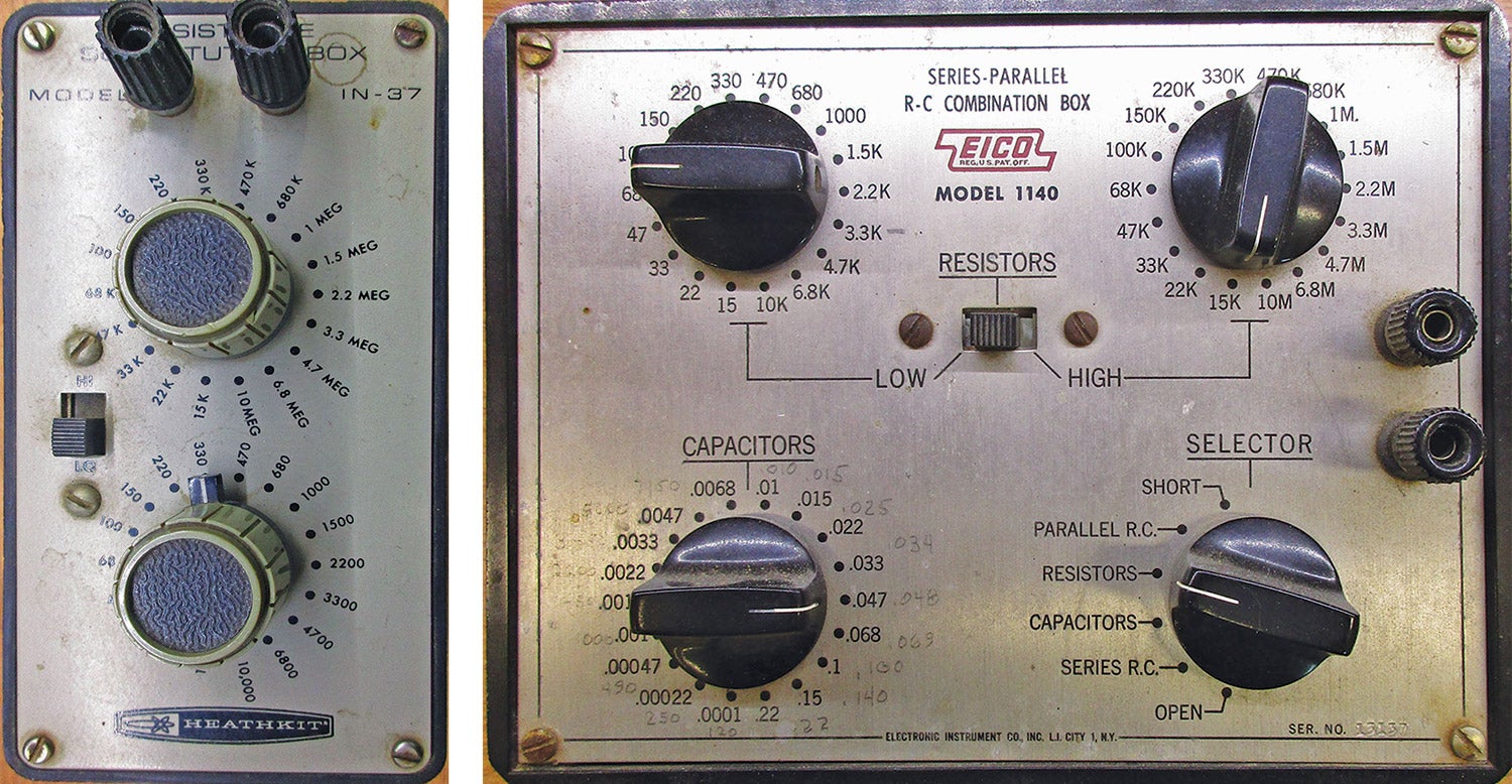
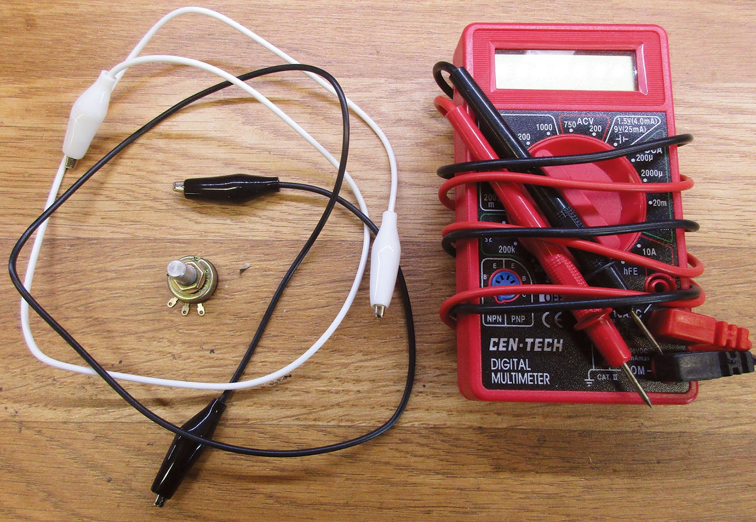
That’s the theory. Now the practicals. Me? I plug a set of earphones into the music box and set it for a comfortable level. Now I diddle (excuse me, scientifically experiment) with different R2 resistor values so that the audio level in my aircraft headphones is roughly the same level as in the music box earphones. How do I do this? With what is called a “resistance substitution box” or the old “variable resistor and multimeter” trick. You can Google them both, but the variable-multimeter is by far the least expensive and versatile. How does it work? You put the variable resistor (potentiometer or volume control) in the circuit for R2, adjust it until the volume level in the aircraft headphones is about the same as the music box earphones, measure it with the $8 Harbor Freight multimeter and use that value resistor in your circuit for R2.
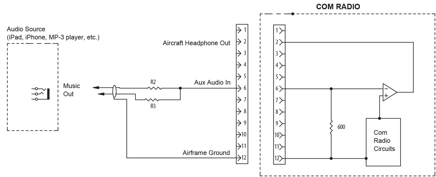
Ah, but stereo. See Figure 2. This is much more difficult…not. You simply take the left channel music box output through a 1200Ω resistor to the aux audio input and the right channel music box output through another 1200Ω resistor to the aux audio input.
What you do not want to do is what I’ve seen more than one homebuilder do. That is to tie the left channel output directly to the right channel output and then to the aux audio input, either through a resistor or directly. This is guaranteed to do one of two things: It will either garble up the audio so that it sounds like a bathtub drain on steroids or it will blow up either the right channel or left channel amplifiers (or both) in the music box.
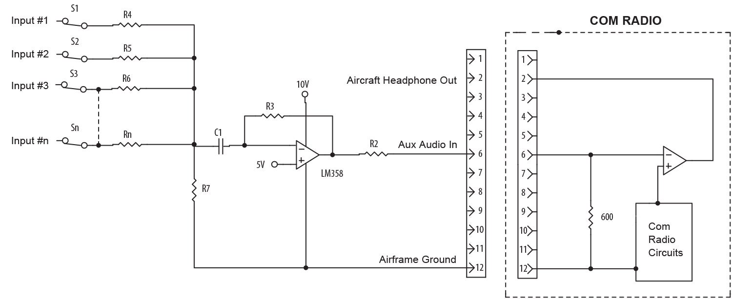
So, we’ve covered music. What if we have five or six audio outputs we want to sum to that one com aux audio in? Say the music box, the angle-of-attack warning, the altitude warning, the engine over-temp or under-pressure warnings and so forth. Up to three or maybe four, you can just keep adding 1200-ohm resistors in the same manner as with the audio box.
Above that, we get into a little more electronics that I’ll explain in a few months. Suffice it to say it takes just one IC chip and you can have 10 to 20 inputs all summed together into one small, inexpensive ($5) circuit. I’ll give you a teaser as Figure 3 and we can talk about it in some detail down the road. Until then…Stay tuned…
Photos: Jim and Cyndi Weir.


s")


Interesting article.
The one scenario you didn´t cover is the different types of output from the audio device.
The article is fine for outputs where one side of the output is grounded but in some cases (such as from the MAX98357 class D output) you need to use an audio transformer to couple the output of the amplifier to the input of the com radio as the output is actively driven on both connections from the amplifier with no ground connection.
Comments are closed.