…and now let’s hit this PC board problem out of the park. Let’s make a useful part with the full PCB program.
Here’s the situation: When I started the project to take a 5-watt solar array and charge the aircraft battery with it, the first cut was to use a switching regulator, which involved a bit over $10 in parts and used a bit more real estate on the PC board than I liked. Since this circuit only gave about 300 mA at full noon sunlight, I decided to see what a plain old linear regulator would give. Sure enough, it gave a bit less than 300 mA, but not a whole bunch less. So I decided that the linear regulator was the way to go.
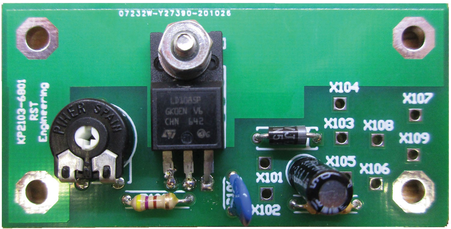
But not just your plain old linear regulator. I took one of the new kids on the block from a very reputable manufacturer who is likely to keep this little sucker in production for the next decade or so. A bonus of the ST Microelectronics LD1085 is that it comes in their TO-220FP package. The TO-220 has been the industry standard for medium power regulators since National Semiconductor introduced the venerable LM317 TO-2220 metal case regulator back in the 1970s.
The TO-220FP took it two steps further. First, as I said, the “P” means it came in thermally conductive plastic packaging. This means that I didn’t have to use any sort of electrical insulator (like a mica washer) between the package and the metal I am going to mount it on. A second bonus is that it uses some of the latest LDO (low dropout) internal circuitry. Dropout, in simple terms, is the lowest input that will give a regulated output. The LM-317, for example, required a 2.2-volt dropout voltage. Putting this in perspective, if I wanted to charge the battery to 13.6 volts, the solar cell would have to be putting out at least 15.8 volts to the regulator input before the regulator would work.
Conversely, with the LD1085, that dropout voltage is about 0.4 volts, so the solar cell will start charging the battery at 14 volts as opposed to 15.8 volts. That may not seem like a lot, but if you go through the math, it is about 3 to 4 hours a day more charge with the LDO than with the old standard. The price is roughly the same for either part and the rest of the circuitry is greatly eased down to the point that parts cost is under $5.
But does that mean you have to make a whole new part in the PCB program? Nope. Remember what I said last month about the parts file being a text file? It turns out that the LM317 set the standard for size and “pinout” for the generations of voltage regulators to follow. Simply copy the LM317 file into the LD1085’s file, change the name (and nothing else) and you have the new part. Once again, I can’t emphasize strongly enough that whatever program you use, if the parts bin uses text or some other format that’s easy to copy, making new parts is quite easy.
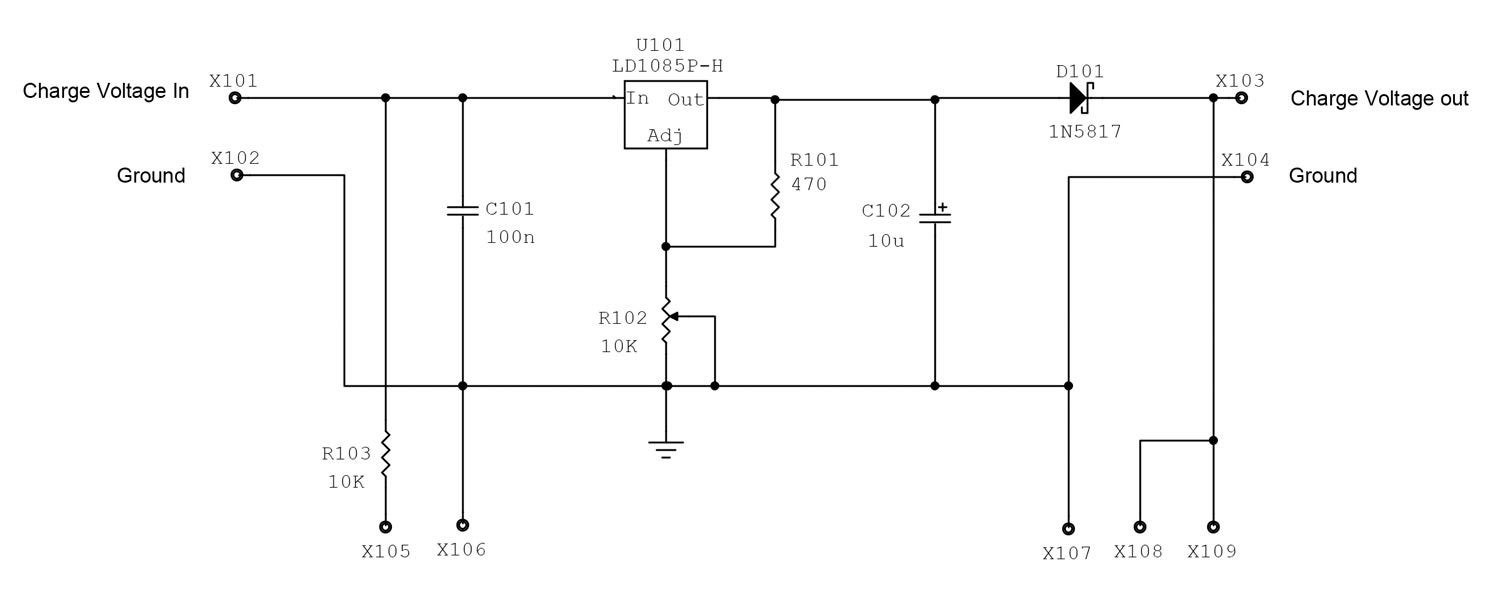
Take a look at the schematic diagram. All the goezintas (inputs) are on the left and all the goezoutas (outputs) are on the right. That is the standard way of doing things, although I have noticed over the years that some of my left-handed students tend to do their schematics from right to left. Some psychiatrist is going to make a fortune someday proving why that is the case.
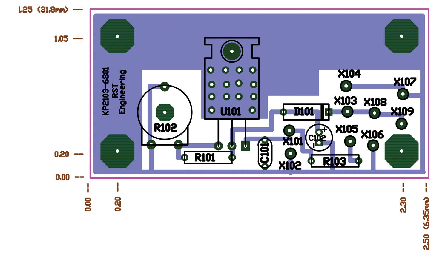
At any rate, it turns out that an efficient layout of the board works pretty much the same way. All the inputs are on the left side of the board, and all the outputs are on the right side.
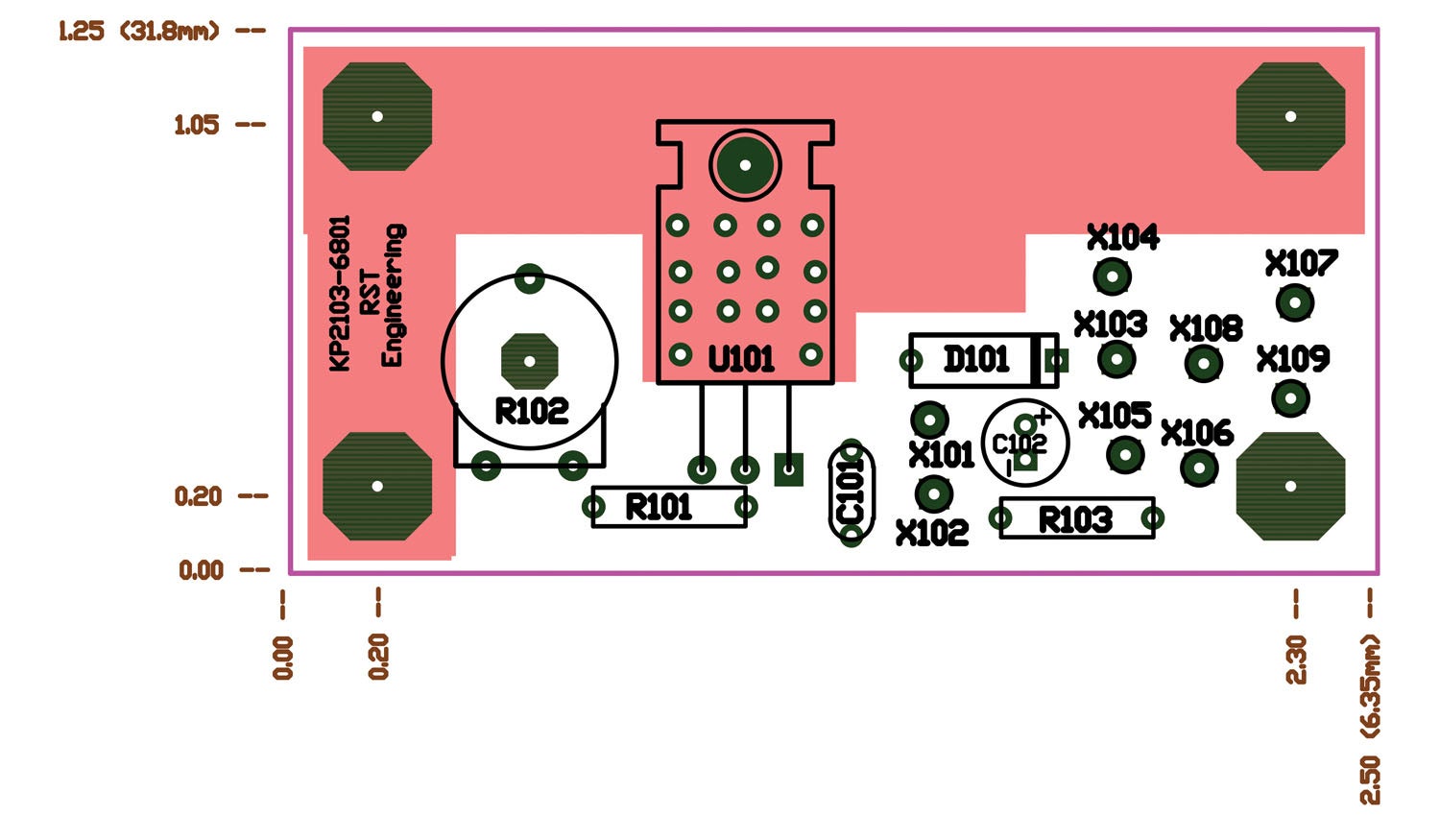
In general, I like to start the layout with the “star of the show,” the most active part in the circuit. In this case, it is the voltage regulator, LD1085, or as we can call it now “U101.” Why “U” for an integrated circuit? Because we go by seniority in labeling parts. “I” was coined by Edison way back in 1895 and stands for “incandescent light bulb,” so “I” was taken. “C” wasn’t available as the capacitor was invented at about the same time. Same thing for the poor old transistor that came along in 1948. “T” was taken by Károly Zipernowsky in 1885 for his newfangled transformer, so Q was one of the last letters left.
But I digress. We need a couple of capacitors (C101, C102), a fixed resistor (R101) and a variable resistor (R102) to set the output voltage, and a diode (D101) to keep an inadvertent connection to the battery before we give U101 an input voltage, which would destroy the IC. Now a little LED light (D1) and a resistor (R103) set the current through the LED so we can tell when the solar array is producing power.
Where are these parts downloadable? Visit www.rstengineering.com and go to the April HOG issue for the Circuitmaker PCB program. The LD1085 is in the Linear Active/Voltage Regulator bin, R101 and R103 are in the Resistors/Fixed Film/Qwatt bin, D101 is in the Transistors and Diodes/Schottky bin, R102 is in the Resistors/10mm Trimpot/Htrimslt bin, and all the X-connectors are in the Connectors/Active/In-Out bin. Don’t forget to go to the top Options bar, Schematic, to set the Designator/Starting number to 101 to get the correct PC board starting number.
How about some stuff you might not have thought about? Why is the protective diode (D101) and the LED light (D1) numbered so? That’s because, in my world, parts mounted to the chassis (like the LED) get part numbers from 1 to 99, the parts on the first PC board of a project get 100–199, the second PC board 200–299, and so forth.
The little “X101” and all the rest of the “X” holes are where wires are going to go to the rest of the chassis input and output connectors.
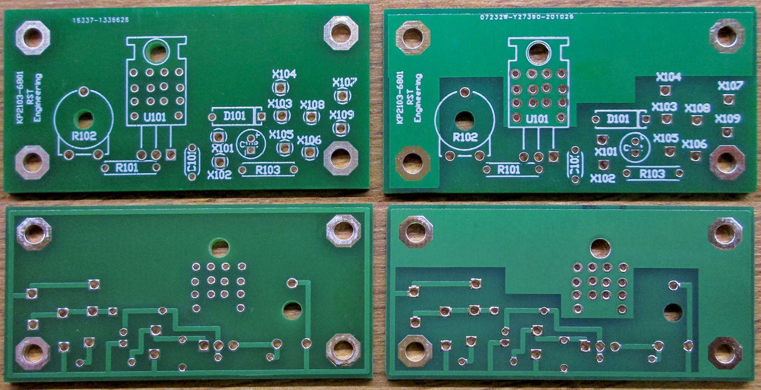
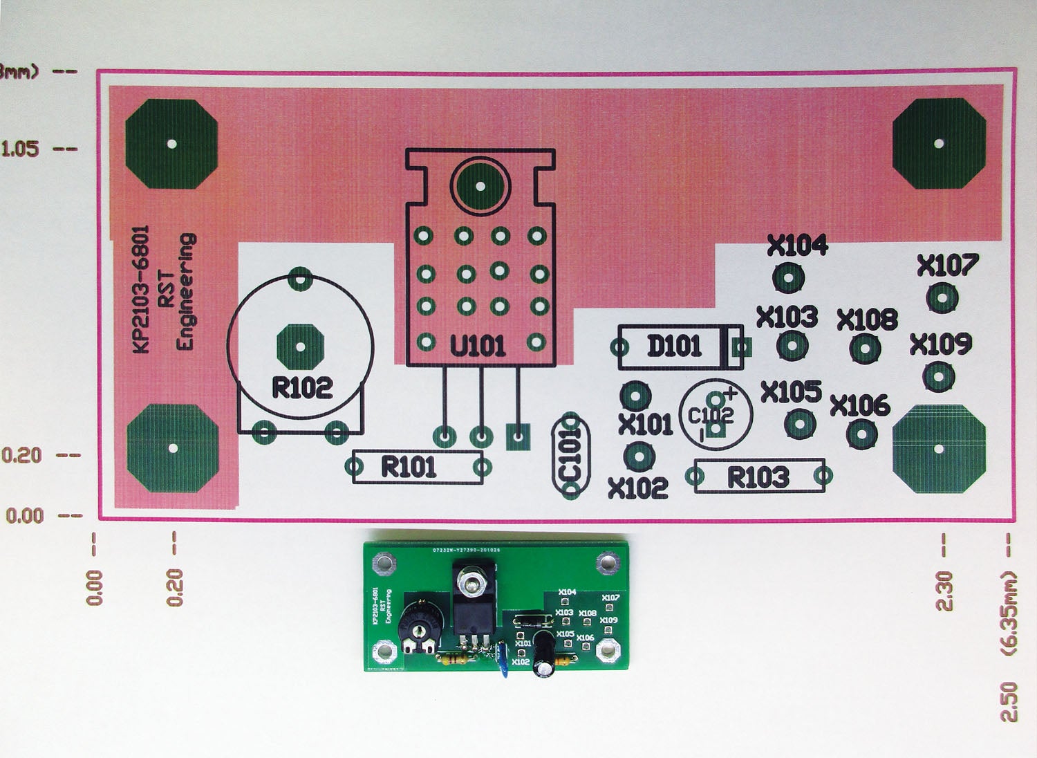
Now, about me being the cheapest horse in the stable. You will notice in the KITPLANES® March 2021 issue (right side) that there is a strip of copper bolted to U101. That is a heat sink as U101 gets reasonably hot on a good summer’s day with maximum output. I could have bought a commercial heat sink, but with all the real estate left over by eliminating the switcher part of the prior design, I used that area for some large copper areas on the board that will work well as a perfectly wonderful heat sink.
As to making boards without resorting to swimming pool and drugstore chemistry, there are a few choices. While I hate to admit it as a dyed-in-the-wool environmentalist, making PC boards commercially involves some pretty nasty chemistry, mainly the etchant. Sure, you can use muriatic acid and hydrogen peroxide at home. What you are left with is copper chloride, which is not particularly nasty, but it doesn’t etch very fast. Ferric chloride etches fairly rapidly, but you are left with both iron and copper to get rid of. You can clean it up with steel wool, but that is expensive.
to manufacture the boards.
Several companies in the USA have established elaborate procedures for recovering almost all the metal waste, but it is an expensive process and their prices reflect it. One of the best I’ve found for reasonable quantities is OSH Park (www.oshpark.com). For $5 a square inch of board design, you get three boards including shipping. For our little 2.5×1.2-inch board, that is $18.50 or about $6 a board. No, you can’t buy just one. They do abide by the USA EPA standards (so I’m told).
Or you can choose to go offshore, mostly to the Far East, mainland China being high on the list. Two sites I particularly like are www.pcbcart.com and www.jlcpcb.com. I’ve used PCBCart for almost 20 years and their product is flawless. Their price per board is reasonable, but they send each batch of boards as a separate package and the shipping is outrageous (I used PCBCart for the boards in this article). JLCPCB evidently collects several dozen orders into one big box for shipment and separates them when they come into the USA in USPO shipments. Shipping prices are one-tenth that of PCBCart. These boards were $50 for 10 boards ($20 for boards and $30 to ship them) from PCBCart, and they would have been $12 total had I ordered them from JLCPCB. As to environmental considerations, never watch sausage being made. More later when I do another design article.
Enough of PC boards for your projects. Back to the hangar solar and other experiments. Until then… stay tuned…


The explanation around the ‘U’ labeling reads a little bit odd. It starts out as an explanation around seniority, and ends up with the conclusion that the letter ‘Q’ was one of the last one available?
The actual source of the letter ‘U’ for integrated circuits was originally, that these parts were ‘Unrepairable’.
Comments are closed.