On some airplanes, the basic empennage does not provide acceptable flying qualities in all flight regimes. Supplemental surfaces to augment directional stability, improve high angle of attack characteristics or improve spin characteristics can solve these issues.
One class of such surfaces is typically mounted low on the aft fuselage.
Ventral Fins
Ventral fins are vertical fins that extend downward from the bottom of the fuselage. They are typically smaller, with a lower aspect ratio, than top-side vertical fins, primarily because they need to be short to maintain acceptable ground clearance.
A big advantage of ventral surfaces is that they are in clean airflow, particularly at higher angles of attack. This means they retain their effectiveness in situations where the other tail surfaces may be immersed in the wake of other parts of the airplane.
Relatively small ventral fins can increase directional stability more than their area alone would suggest for two reasons:
First, the ventral fin increases the effective span of the whole vertical tail, so in addition to generating side force itself, the effective span increase due to the ventral fin also increases the effectiveness of the whole vertical tail.
Second, the ventral fin acts as a fence that increases the side force that the fuselage side above the ventral fin generates in a sideslip.
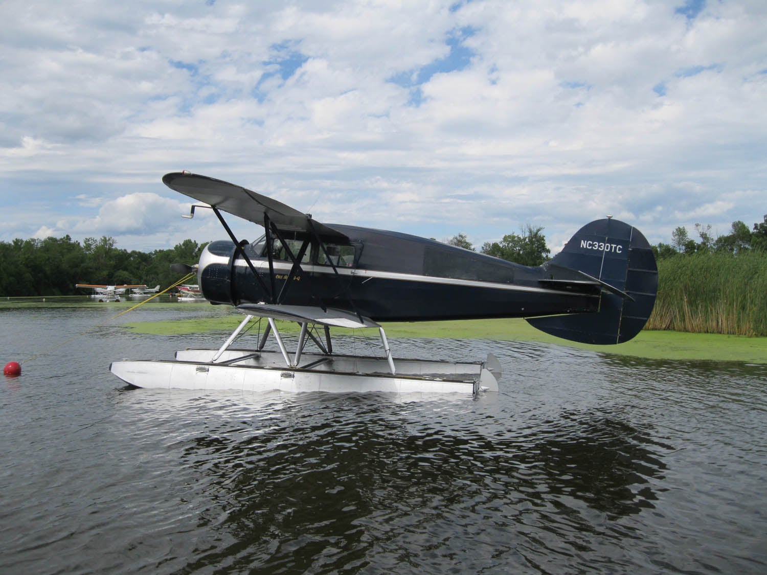
Ventral fins are a common feature of floatplanes. The vertical fins on these airplanes were sized for the original landplane configuration. Floats are directionally destabilizing because placing them so that their center of buoyancy on the water is at the airplane’s center of gravity puts them far enough forward that their lateral aerodynamic center is forward of the CG. This effect may be large enough that an increase in fin effectiveness is necessary to maintain good flying qualities. One way to add the needed extra directional stability is by adding a ventral fin on the centerline of the bottom of the fuselage below the original fin and rudder.
In addition to improving directional stability, a ventral fin improves yaw damping and spin recovery. Ventral fins are particularly effective at improving spin characteristics because they are in clean airflow at high angles of attack. They provide yaw damping that slows the rotation rate in the spin and makes it easier for the rudder to break the spin.
One example of this is the evolution of the tail of the Cessna Skycatcher LSA. The first prototype was lost in an unrecoverable spin during testing. (The pilot bailed out successfully and was not injured.) The second version of the airplane still had problems recovering from spins. The final modification to the tail was the addition of a small ventral fin. This cured the spin recovery problem.
Afterbody Strakes and Canted Ventral Fins
Horizontal Strakes
Low-aspect-ratio horizontal strakes mounted to the aft fuselage are often used to improve longitudinal stability at high angles of attack. The strakes act as an additional low-aspect-ratio horizontal tail. Because of their low aspect ratio, the stabilizing effect at low angles of attack is relatively small, but it increases significantly at higher angles of attack.
If the goal is to increase pitch stability in cruise flight or move the aft CG limit of the airplane aft, strakes are relatively ineffective. A better solution is to increase the span and area of the horizontal tail.
Where strakes are most effective is at higher angles of attack. This makes them useful for improving stall recovery and stability near the stall.
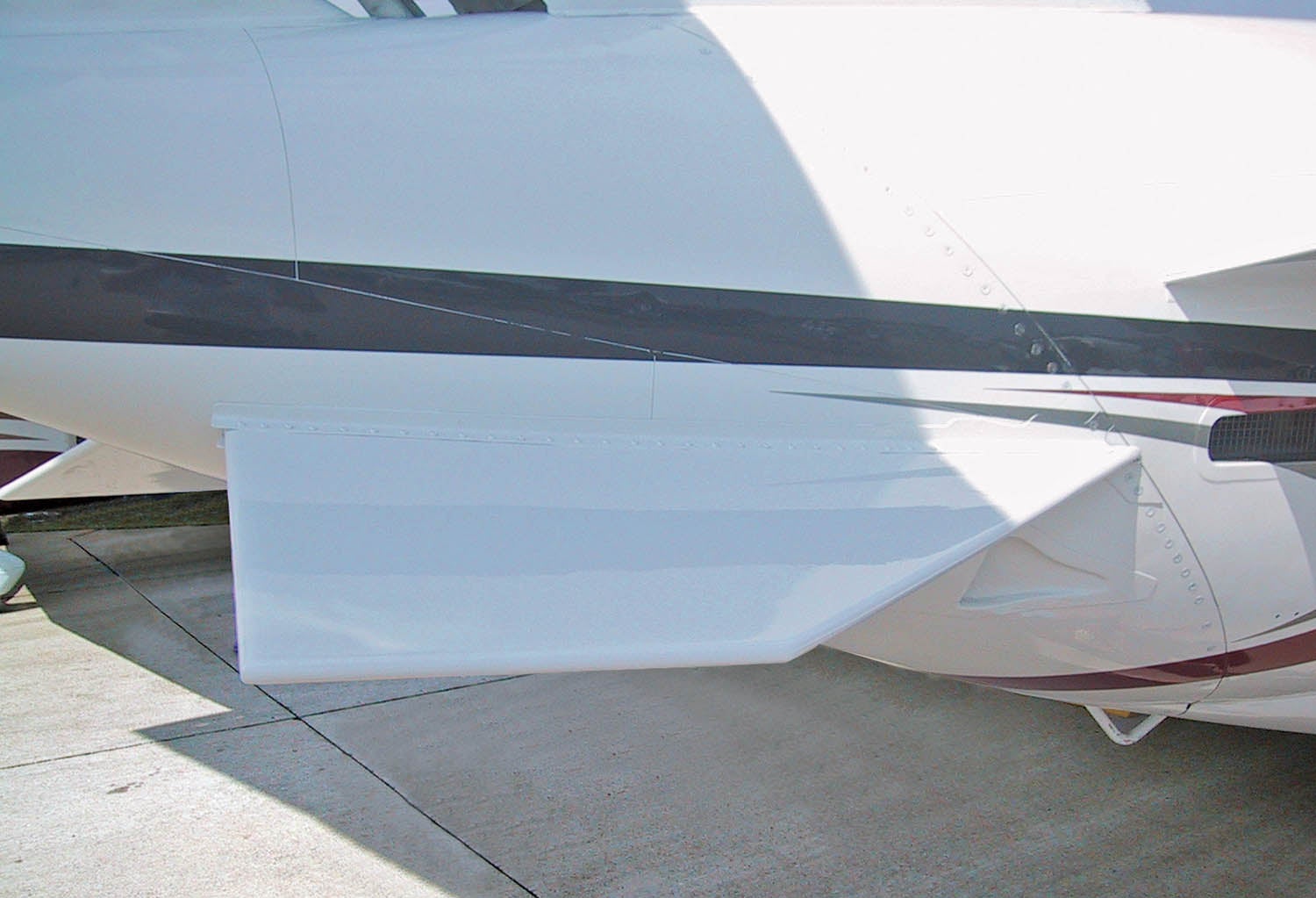
Afterbody strakes produce a stabilizing nose-down pitching moment. The moment increases as angle of attack increases up to and beyond the angle of attack at which the wing stalls. This nose-down moment helps limit the angle of attack of the airplane and aids in getting the nose down to break an incipient stall.
Low-aspect-ratio surfaces have nonlinear lifting characteristics. Not only does their lift increase with increasing angles of attack, but the slope of the lift curve also increases as angle of attack increases. They achieve their maximum lift at significantly higher angles of attack than higher-aspect-ratio surfaces.
At low angles of attack, the flow over a strake is fully attached and its lift varies linearly with angle of attack.
At higher angles of attack, the flow separates from the leading edge and outer edge of the strake and forms a vortex. The vortex generates lift differently than attached flow. As angle of attack increases, the strength of the vortex increases. The lift it generates is proportional to both the angle of attack and the strength of the vortex. Because of this, the lift of the strakes varies with AoA squared in the vortex-lift AoA range.
The nonlinear lift of the strakes means that the stabilizing effect of the strakes gets larger as angle of attack increases into the vortex-lift regime. This makes them ideal devices to compensate for the pitch-up and high AOA loss of longitudinal stability that is sometimes a problem on T-tail and V-tail configurations. The nose-down moment of the strake replaces the lost nose-down moment from the tail and helps the airplane maintain pitch stability as it approaches the stall.
One example of this application of strakes is on the Cessna Citation Mustang, which has a T-tail and a pair of afterbody strakes mounted low on the aft end of the fuselage.
Canted Dual Strakes
Some airplanes use a pair of aft body strakes mounted with a significant anhedral angle to form an inverted “V.” The anhedral angle moves the strakes down relative to the rest of the airplane. This keeps them clear of the exhaust of fuselage-mounted engines and helps ensure that they will be in clean airflow, out of the wake of the wing or forward fuselage. It also allows the strakes to do double duty. They improve directional stability and also have the high AOA pitch stabilizing effect of horizontally mounted strakes.
An example of the use of canted dual strakes in combination with a T-tail is the Learjet 60.
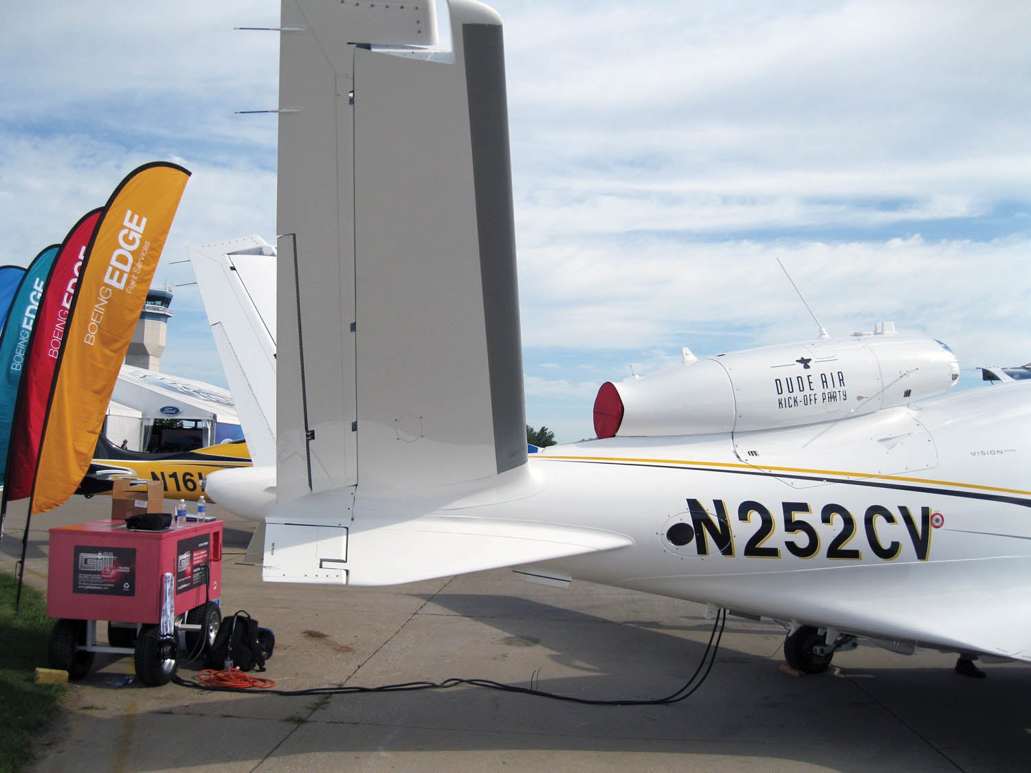
The Cirrus Vision Jet has a pair of strakes below the fuselage. These strakes have anhedral that mirrors the dihedral of the V-tail surfaces so the combination of V-tail and strakes form an X-tail.
Afterbody Strakes for Drag Reduction
Another application of dual strakes is to control the flow on the fuselage afterbody to reduce the drag of the airplane. Dual strakes are common on airplanes that have upswept afterbodies like those of military transports. If the aft portion of the fuselage is swept upward, either for an aft door or to give more ground clearance from a tail strike on the runway, the flow can form a pair of vortices that shed aft from the fuselage. Adding a pair of properly oriented strakes to the afterbody can reduce the strength of these vortices and control their position so they shed cleanly from the aft fuselage and produce less drag.


