
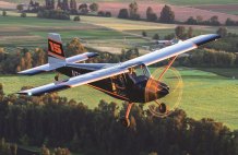
Instead of a tailwheel, it sits on tricycle landing gear. Its biplane wings are set backwards in a negative stagger. There are full-span flaps on the upper and lower wings, and spoilers instead of ailerons. And the large canopy slides forward. The Durand Mark V is unlike any other airplane seen since its designer, William H. Durand, introduced it at EAA Oshkosh in 1978. Nearly 40 years later, it caught the eye of homebuilt flight line passersby at EAA AirVenture Oshkosh 2017 when Durand Industries LLC reinstated its existence with plans and the ultimate goal of a kit.

Built in 1978, government surplus instruments fill the Mark V’s panel. The brake lever extends below the throttle quadrant.
The company is recreating Durand’s fifth design in SolidWorks, said Jim Swatosh. The 3D CAD files are the first step in turning the scratch-built design into a kit. There is no hard timeline to this goal, but plans are available now.
Swatosh learned about the airplane during the resolution of a business issue unrelated to it. Without going into the details, Swatosh acquired the airplane, all 92 sheets of the original plans, and the rights to the airplane from Jim Durand in 2013, three years after his father passed away at 96.
Swatosh first saw the airplane in a storage unit in Balsam Lake, Wisconsin, just across the St. Croix River from his home in Stillwater, Minnesota. Even in its dismembered state, the design captured Swatosh’s heart, “like that 1940 Ford you see going down the street when you’re a kid.”

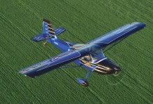
Jim Swatosh demonstrates the forward-sliding canopy and unobstructed ease of stepping into the cockpit.
When he acquired the airplane, Swatosh didn’t think about selling plans and producing a kit until he learned more about the designer, whom he reverently refers to as “William.” By 1987, Durand had sold 75 sets of plans; that number grew to 91 in 1998. As near as Swatosh can tell, approximately 12 Mark Vs were built, including five confirmed flyers. Swatosh owns two of them, Durand’s prototype, and another, built in Canada, which flew on floats.
What he most admires about the Mark V is that “everything is designed; it wasn’t thrown together,” said Swatosh, an appreciation born of his career in business and manufacturing. Beyond that, “my history has been restoring old things,” he explained. “I’ve restored a lot of century-old homes; the Durand is a different sort of restoration.”

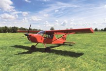
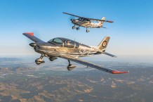
The Durand Mark V outside Nick Jilek’s hangar at Wisconsin’s New Richmond Regional Airport.
The Mark V has also reinvigorated Swatosh’s aviation aspirations. In 1978, he was a student pilot who’d soloed and logged 20 hours of dual. Life postponed his private pilot certificate, which he is once again pursuing.
His initial efforts to reunite the Durand’s parts revealed that not all airframe and powerplant mechanics have the knowledge and skills necessary to recreate missing parts, like the left stabilator, and reassemble an Experimental/Amateur-Built aircraft. Nick Jilek is now the airplane’s mechanic and pilot. Working from his hangar at Wisconsin’s New Richmond Regional Airport, also across the river from Stillwater, Jilek made his first homebuilt test flight in 1982 and “averages 350 hours a year in everything from a Mooney Mite to the [twin turboprop] Merlin.”
It was chance that introduced Swatosh and the Mark V, but it’s a good kit candidate because Durand designed it specifically for the scratch builder. He explained this in detail in three EAA Sport Aviation articles in 1978-79, which are on the Durand Industries website, www.DurandMarkV.com.

With the brake lever extending below, the throttle quadrant holds the parking brake, throttle, and mixture.
A Practical Airplane for the Amateur Builder
That is how Durand summarized his clean-sheet design. Its mission is “day VFR pleasure flying with lots of visibility,” and a panel with room for avionics and (large government surplus) instruments necessary for occasional IFR flying. Instead of making builder-pilots and their passengers adapt themselves to the airplane, he adapted the airplane to their needs through a “unique but purposeful combination of old and new—negative stagger cabin biplane with modern full-span flaps, spoilers, stabilator, forward-sliding canopy, tricycle landing gear, and all-metal construction.”
With the negative stagger and a canopy that rolls forward smoothly on the drawer rails of an office filing cabinet, pilots and passengers can step effortlessly into the 44-inch wide cockpit without bending or folding their bodies, bumping their heads, or leaving a muddy footprint on a seat cushion. (Replacing the missing steps that extend forward of the leading edge is on Jilek’s to-do list.)

When stepping on a rudder pedal, the “inactive” pedal moves only slightly in the opposite direction.
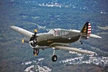
“I have rated gentle flying characteristics, short-field capability, personal comfort, cross-country usefulness, occupant safety, and structural simplicity more important than extremely light weight, high cruising speed, or other strictly competitive numbers,” wrote Durand. He designed visual references into the airplane. The forward-sloping cowl parallels the ground line between the tailskid and main gear. For an average-height pilot, “this flat surface will align with the horizon when the airplane is in the correct attitude for a minimum speed touchdown.”
Still, like many homebuilts, the Mark V embodies its designer’s personal predilections. “I suppose that most pilots would prefer toe brakes” (and Jilek leads that list). But Durand wrote that he too often rode them unintentionally, so the Mark V has a brake lever. Connected to a single master cylinder, the lever extends below the center quadrant that is home to the parking brake lock, throttle, mixture, and carb heat. A steerable nosewheel guides the way, and all three gear legs are sawn from thick Scotchply, a 3M composite material used for the same purpose on Grumman American two-seaters.
Durand also did not like bending an ankle backwards when he pushed on a rudder pedal. So in the Mark V, full deflection of the “active” pedal causes the “inactive” pedal to move aft only slightly. With dual sticks, all of the other controls are conventional. Along the bottom edge of the panel, spring-loaded map pockets double as padded knee protectors, and the four-position flap handle and trim lever are between the seats. The trim lever controls the stabilator’s anti-servo tabs. “Its position indicates the amount of trim…and [it] acts as a miniature control stick,” Durand wrote.” Jilek seconds this.
Given its canopy, ventilation is crucial. Bilateral plenums supply temperature-controlled air to the sidewall vents. A diverter sends defrosting air to the windshield. The cabin airflow exit control is in the overhead console with a speaker and cabin and panel lights. A second detent on the canopy’s overhead locking cam latch holds it open a bit for increased taxi ventilation.

Cutaway view of the Durand Mark V.
Designed for Garage Construction
When designing a homebuilt, Durand wrote, designers must consider the range of possible builder-pilots and their shops. “His flying experience may be limited, and his experience as an airplane builder, nil. Everything considered, the [pulled]-riveted all-metal biplane seemed to offer the right combination of compact dimensions, general wing area, and simple, clean, odor-free construction resulting in a really durable machine.”

The open cowl doors provide easy access to the Lycoming O-320.
Members of EAA Chapter 80, which Durand helped found in Omaha, Nebraska, built the prototype on a “4×8-foot plywood table in a 14×18-foot shop that also included a workbench, drill press, stove, and our local EAA chapter library.” Builders will need more room for final assembly, a bending brake, and a welding kit for the control fittings, engine mount, and exhaust system.
With the negative-stagger biplane’s 24-foot-6-inch wingspan and 36-inch wing chord limiting the travel of its center of pressure, Durand wrote that the Mark V’s shorter, lighter, less expensive 20-foot-3-inch fuselage does not sacrifice stability. Investing nearly four years designing it, “stress analysis and weight and balance calculation paralleled the continual modification of the layout to achieve the simplest and most direct solution to the problems associated with airplane design.”

The overhead console is home to the radio speaker, panel and cockpit lights, and the knob that controls the amount of air that leaves the cockpit.
In addition to easy entry, the negative stagger contributed some “desirable aerodynamic characteristics [such as] inherent flare-out at touchdown, flaps that don’t require a trim change, and excellent anti-stall properties.” Those full-span flaps were important to Durand. “Since the airplane was going to be based and test flown at my backyard grass strip, Durand Sky Ranch, short-field capability was a must.”
Explaining the negative-stagger aerodynamics, Durand noted that the lower wing is ahead of the CG and the upper wing is behind it. While both wings have the same span, chord, and angle of incidence, “the actual angle of attack is different [because] the trailing wing is working somewhat in the downwash of the leading wing. This changes the lift contribution from a 50-50 situation to about a 53-47 basis, with the lower wing being slightly more effective.”

The overhead cam latch that secures the canopy has a second notch to provide additional ventilation during taxi.
When the angle of attack approaches the stall, Durand wrote, the airplane does not rely on one wing for all of its lift. The lower wing stalls a few degrees before the upper. In this situation, the upper wing becomes more effective; being “behind the CG, its lift causes a nose-down pitch while working at or near its maximum lift coefficient.”
This not only reduces the altitude lost in stall recoveries, it delivers an “inherent advantage” on landing. Approaching the runway, ground effect acts on the forward lower wing, gradually increasing its lift. Acting ahead of the CG, “it gently raises the nose for what might be termed an automatic flare requiring little, if any, help from the pilot.”

There are separate heat and airflow controls for each seat.
Upper and lower full-span flaps not only slow landing speed (and landing distance), they eliminate the need for trim changes often necessary when extending partial-span flaps, which change the wing’s center of pressure. The Mark V proportions “the lift of the two staggered wings in the flaps-down mode so that their composition center of pressure does not move rearward.” Durand did this with different full-flap deflections, 40 degrees on the upper and 45 degrees below.
Full-span flaps made spoilers as the only roll option. The simple flap is 4.75 inches wide, 69.5 inches long, and hinged at the leading edge. Operating individually, full deflection is 40 degrees.

The right spoiler in full deflection. The control surface behind it is a full-span flap.
Building the prototype “tested the plans and revealed dimensional errors, inadvertent omissions, and related improvements.” Given his “I’d rather be flying preferences,” Durand focused on easy access for maintenance and servicing, and a quick but thorough preflight inspection. He mounted the battery, for example, in a swing-out box in the tail cone, so builders can service it outside the airframe and not have to worry about a prop strike when jump-starting the airplane in cold weather. At the other end, to change oil without removing the cowling, there’s an opening aligned with the sump quick drain.

The trim lever and flap handle are in the console between the seats.
Three Subassemblies
The Mark V fuselage is composed of three subassemblies: the cockpit, the baggage area and cabane, and the tail cone. Durand compared the cabin assembly to framing a house, with “a center girder, floor joists, and wall studs [2.5-inch channels drilled for wiring], and a top plate.” For occupant protection and structural stiffness, the cockpit is skinned inside and out. The floor and bottom skin join with keel channels to create a box beam that runs the length of the cockpit and provides attachments for the lower engine mount, nosewheel, and Delrin control bearing.

Like the nosewheel, the main wheels are bolted to the Scotchply gear legs. Also visible is the glasspack muffler.
The wing employs a two-piece spar comprised of 0.050-inch material bent into modified J-sections joined by pulled rivets. Builders can fabricate each spar in its full 10-foot length or in shorter sections using the low-stress splices indicated in the plans. The rear spar and flap spar are formed of 0.040-inch stock. The 0.032-inch leading-edge channels are nonstructural; they align the nose ribs during assembly. Since all four wings are the same, builders need only one rib form block. Except for the lower wing walkways, the wings are skinned with 0.020-inch Alclad.
Builders fabricate the tail cone from the bottom skin up. They mount the bulkheads to this skin, which eliminates the need for an assembly fixture. Only straight bends form the parts of this stressed-skin structure. Except for the back channel that runs across the top of the bulkheads, primarily as an assembly convenience, there are no longerons or stringers, “only skin stiffeners between the frame locations, which are riveted in place prior to their incorporation into the structure.”

To make subassembly alignment easy, the fuselage bottom is flat from the tailpost to the firewall. The prototype’s builders aligned the tail cone and forward fuselage on a one-piece aluminum ladder supported by two sawhorses. They adjusted the subassembly alignment until the canopy rails were even.
The canopy looks like blown Plexiglas, but it is 1/8-inch Lexan cut and bent cold. A tough, pliable polycarbonate, Lexan costs more than Plexiglas, Durand wrote, “but you don’t have to build or borrow an oven to heat it before bending.” The canopy frame holds it in place, and its curvature produces a rigid surface that eliminates the need for corner posts that would block the occupants’ view.
The main landing gear is essentially an independent chassis, with Scotchply legs bolted to a steel carry through that absorbs all the bending stresses. Aluminum saddles mate this chassis and the fuselage. An automotive glasspack muffler is located between the main gear legs to mute the roar of the 150-hp Lycoming O-320.

Scratch building is the first of three options for building the Durand Mark V. The plans include hardware and material lists and diagrams for getting the greatest number of parts out of 4×12-foot sheets of metal. As the SolidWorks CAD effort continues, Durand Industries will incrementally offer complex and welded parts, and then kits, said Swatosh. “I just found a company that makes rotationally molded polyethylene fuel tanks.” Made of welded aluminum, “the Durand fuel tank is a work of art, but it takes time to build, and I want to give builders options.”
Modern kit aircraft are, for the most part, thoroughly developed, well-behaved machines. We’ve learned a lot over the years that has helped designers improve their manners to the point that they can behave reasonably well in mixed company (mixed being a variety of pilot skill levels). There are very high-performance machines that have significant quirks because of what they are, and those quirks are accepted in order to make the plane as fast as possible, or something that can win at unlimited aerobatics—but the average pilot’s average airplane should generally meet the handling requirements of the accepted norm.

This isn’t really true of older designs that are beginning to look downright ancient when you consider that more than a generation has passed since they were conceived. The Durand is this kind of aircraft, an interesting concept combining old biplane technology with newer construction techniques to produce an airplane that was intended to be stall proof in the time of Rutan’s work doing the same thing with canards. There are estimated to be about 12 Durand Mark Vs built and two more currently under construction, but no one knows how many might be flying today. Two of them are now owned by Durand Industries LLC, although one is currently disassembled. The particular aircraft we flew was built in the 1970s and spent decades in storage before being purchased in an estate sale by the current owners. It was, they report, in good shape, but was missing one half of the stabilator, which they replaced using the plans set they had acquired.
First Flight Review
With the Durand Mark V repaired and back in the air, I was invited to fly it. During the preflight briefing, I learned that things got a little sporty with the flaps extended, so the Durand team had decided to fly it without flaps until that was sorted out. That meant higher takeoff and landing speeds, but nothing out of the realm of the ordinary, 80 knots being the preferred number on final. With roll control provided by spoilers and pitch inputs handled by a stabilator, it is unusual, but not outside of accepted practices.
The owner’s demo pilot at AirVenture offered to fly along with me (the owner not being licensed). Since the takeoff and landing characteristics were (as mentioned) a little tricky, I let him do those phases of flight. As we climbed away from Oshkosh on a beautiful morning, surrounded by airplanes departing the annual EAA convention, I took the controls and immediately realized that the pitch channel was quite unusual.

Without a lot of backup data for this acquired plane, there isn’t a consensus on the actual CG range, but it felt like it was loaded a bit aft. The airplane was statically neutral in pitch, with very light forces. Dynamically, it felt as if an oscillation wanted to develop in pitch with increasing speed, so we limited ourselves to a point where it seemed comfortable (100 knots) and performed the rest of our mission (a photo flight) at that speed or below. Adding power tended to create a bit of a porpoise since it meant we sped up into the dynamic range, so formation flying was tricky.
It had been a long time since I had flown an aircraft with spoilers for roll control, so I was curious about what to expect. It turned out that the airplane was controllable, but the stick had an unusual feel. There was a narrow dead band in the center, and as you pushed to add a roll input in either direction, nothing happened until you pushed just a little bit harder than you expected—and then the spoiler popped up to enact your desire to roll. The effect was that there was a detent of some sort, making it hard to add a smooth input in either direction. The rudder, on the other hand, has a smooth, natural control feeling like any rudder on any airplane. Trying to coordinate it with the somewhat ratchety roll control was the only unusual bit about that channel. But adding rudder alone, as is often done in formation, made the airplane want to roll, demanding stick input which exhibited that detent feel. Needless to say, it took some attention.
Our concern was primarily with what seemed like stabilator instability, and the fact that the motion was oscillatory with increasing amplitude really caught our attention, this being a good description of the onset of flutter. After this flight, we huddled with the Durand team and were told that when they found the airplane, it was missing the left stabilator. A new one was fabricated and installed, but further investigation showed that the bolt holes in the torque tube were wallowed out, and the control surface was able to move on the tube. Any loss of stiffness in this fashion could easily lead to a flutter situation, so we excused ourselves from further flying at the show and said we’d be happy to fly the airplane again once this was addressed.
Second Flight Review
It was a beautiful bright fall day in western Wisconsin when we next saw the Durand and checked out the repairs, which had been done in the ensuing months. We again climbed into the plane for an evaluation flight. In addition to the stabilator torque tube repair, the team had also rerigged the spoilers for more symmetrical deployment, an issue they had found that we had not observed.
The prototype aircraft has a comfortable cockpit, with good visibility out of the frameless forward-sliding canopy. With the upper wing mounted aft of the cockpit, it was almost like flying in a bubble canopy—especially since we seem to be able to swivel the head less with age. The panel is, as you’d expect from a 1970s aircraft, a bit antiquated, with a large four-inch attitude indicator that sounded like a turbine engine spooling up. All of the basic controls are there, and the throttle is mounted to a quadrant to give a little more of a big-airplane feel. The trim is actuated by a lever, as are the flaps.
As was common in many earlier aircraft, the plane is equipped with a single hand brake instead of differential toe (or heel) brakes, but the nosewheel steering proved adequate for control on the ground. It is a bit heavy, but manageable, and we found our way to takeoff position without any trouble.
We elected to keep the flaps up for takeoff, and as speed built, the airplane flew off the ground in essentially level attitude, with little rotation. As we pitched for climb, we once again felt the odd pitch forces, which I’d describe as similar to those of the spoiler—with a bit of a detent near the middle and very light to negative forces once you moved the control a fraction. This feel can lead very easily to a pilot induced oscillation. Imagine an inverted bowl with a marble balanced on top. Obviously, this is unstable, since if you disturb the ball, it will roll with increasing speed off the bowl. Now put a dimple in the top of the bowl. This will make the marble somewhat stable right at the top, but once you apply a disturbing force, it will again accelerate down the side of the bowl. The Durand feels like this, but after a few degrees of what feels like instability, it stops accelerating away—a very odd control feel. While manageable, it is certainly not very desirable, and the folks at Durand seem to understand this. Rather than try to deal with a landing immediately after takeoff with the odd control feel, we elected to climb out and evaluate the airplane with some altitude underneath us before returning to earth.
After a few minutes of “getting the feel,” we had adapted enough for some slow flight, and some nibbles at power-off stalls. Here we learned that the odd pitch forces were related in some way to the prop wash, for when we pulled the power back, the unpleasant pitch forces reverted to a much more normal feel. Essentially, in gliding flight, the airplane behaved as you’d expect for a typical light plane. After our flight, we noted that the stabilator panels on each side are almost square—short span, large chord—and it might be that they need to add more span to add stabilator surface outside of the slipstream. One hypothesis is that with the current axis of rotation (about the torque tube), there is enough surface area ahead that when you move the stabilator, the prop wash “grabs” the leading edge and attempts to move the surface in the direction you are going, but with more force than is appropriate.
Regardless of the causes, Durand LLC told us that they will be hiring outside aerodynamic consultants to evaluate the problem and come up with a solution to make the airplane handle more like what the typical pilot is used to. This is an excellent attitude, and a very good idea, since the current characteristics could catch an unsuspecting, inexperienced pilot very much unaware—which brings us back to where we started. In the earlier days of homebuilding, just getting an airplane finished was a monumental achievement. If it flew, that was even better. If there were deficiencies in the handling qualities, the pilot generally adapted to the airplane, rather than going to the work of finding and fixing the issues. Modern kit (and plansbuilt) aircraft are generally much more mature, having been designed, built, and tested for a wider and larger audience. Poor handling qualities mean no sales. That’s important to remember when you get the chance to fly an earlier design.
Can the Durand be made better? Without a doubt, the answer is yes, and the company now selling the plans is committed to making the airplane safe and well behaved. We’ll be happy to give it another flight when they get done, and we’ll report back—hopefully with a fine-flying, unique aircraft that will turn heads wherever it goes.
—Paul Dye


![Members of the North Idaho High School Aerospace Program gathered at KSZT [Credit: North Idaho High School Aerospace Program]](https://www.kitplanes.com/wp-content/uploads/2026/02/IMG_3499.jpg?w=324&h=160&crop=1 "North Idaho High School Student ACES Fly the Aircraft They Built")

I should be thankful for those articles, whixh gave me so many hints what to look for…
as i didn.t cope with an AR of 4 on my homebuilt design, i finally hopped into the flap design field of loopholes….and the Durand mk-5 has a clever setup, …6 moths earlier inwouldn,t understand why it worked the way it worked, but after 4 moths fighting through Naca repirts and new mostly Chinese university test whixh basically confirmed 1920 ies results,…the Mk-5 “almost” tandem wing with flaps crakcs the AR ratio up by 1/3 bcs nobody needs the full Area besides landing and take off,….öso flaps , normally a nightmare of increasing Momentum on biplanes becomes easily controlled as the balance between the two wings and flap situations, as a eough estimate on my drive home…gave some mere 30% max increase on stick force on the elevator, not even regarding the increase on downwash at hiher AoA, but there is jo higher AoA! with flaps the whole flying works aorund zero to 3 degrees AoA on most airfoils….otherwise he would have needed 50% more wing area at least, and accept a shift in CG ( or center of pressure to he correct) of basically 12-15% ! depending on airfoil…which is normal, but one needs to retrim or hold the force at the stick….the wings work somehow with a leverage of 2:1… while the fron wing also has 5% more lift at full flaps…not even counting rear wing downwash, whixh should he relatively small! as the distance Gap is around 1+ and the stagger over 80% ! the loss or differenc ein lift is less than 5% …there are only 3 data collections out there in open sources , and once one has thise tabellas you just need to decide the configuration you can and want to build and upscale the areas according to lift loss….🤷♀️but it costs one year of research as an amateir from base zero to know what to search for…besides that one knows at the end of the last 6 moths by heart how to calcukate the lift drag or max speed data…for nerds like me an interesting thing to do…i work with 200% stagger and 2/3 Gap at least…and don,t forget to do your research on deep stalls! that is a tricky thing too! many thanks! SR
Comments are closed.