Last month we took a look at how the planform of the wing affects the spanwise distribution of lift along the wing. The shape of this span loading has a significant effect on the span efficiency and hence the induced drag of the wing. We now turn our attention to how planform affects the structure and weight of the wing.
The discussion and comparisons that follow are for cantilevered wings. The distribution of bending moment and the structural value of spar depth is completely different for strut-braced or wire-braced wings than it is for cantilever designs.
Planform affects the weight of the wing in two ways. The first is the effect of the spanwise distribution of lift. As we saw last month, the distribution of the chord along the span has an effect on the distribution of lift.
Each element of lift produces a bending moment about the portions of the wing’s spar inboard of that span station. Wing bending moment is highest at the root and decreases as we move outboard on the wing.
On a cantilevered wing the bending moment is resisted by reaction forces in the spar caps. For upright flight, the upper spar cap is in compression and the lower cap is in tension.
The more load being carried outboard, the larger the bending moment is inboard. This is particularly significant for the inner portions of the wing where the highest moments are found. Accordingly, looking at the wing root bending moment gives us a good idea of how much load the spar caps must withstand and how much they must weigh in order to withstand those loads.
The greater the bending moment, the higher the load the spar caps must carry, so for a given material the thicker and heavier they must be. To illustrate this effect, we will look at the characteristics of the three wings we used as examples in last month’s discussion of span loading. Here are the three planforms:
- Constant chord
- Straight taper (Taper ratio 0.4, i.e., tip chord is 0.4 times root chord.)
- Compound taper (Constant chord for inboard half of span, tapered outer panel. Center section chord is 1.2 times the chord of the constant-chord wing.)
All three wings have the same span, area and airfoil.
Comparing Planforms
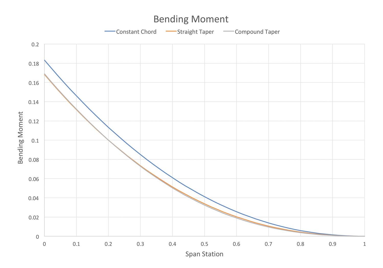
Figure 1 shows the bending moment versus span station for all three wings. Note that the absolute values of moment are not important; what is significant is their relative value.
The bending moment for the constant-chord wing is higher than that of either of the other wings everywhere along the span. The wing-root bending moment of the constant-chord wing is about 4% higher than that of the tapered wings.
Also notice that the bending moments of the two tapered wings (straight-taper and compound-taper) are very close to each other.
All other things being equal, the spar caps of the constant-cord wing will have to be slightly thicker and heavier than the spar caps of either the straight-taper or compound-taper wing.
All other things are not equal, however. Bending is not the only factor affecting wing structural weight.
The second critical element determining the weight of a wing structure is the depth of the spar. This is particularly significant inboard on the wing where the highest bending moments are.
Bending moment is resisted by compression in the upper spar cap and tension in the lower cap. These two opposing forces generate a moment that opposes the moment caused by the aerodynamic lift on the wing. The magnitude of that moment is determined by the size of the forces and the moment arm they have to act on. The farther apart the spar caps are, the lower the forces in the spar caps need to be in order to create the same total moment.
For a given airfoil that has a constant thickness-to-chord ratio (T/C), the longer the chord of the wing is, the deeper the spar will be at that point. The deeper the spar is, the less force there will be in the spar caps to resist the bending moment and the lighter spar caps can be. With this in mind, let’s return to our example wings.
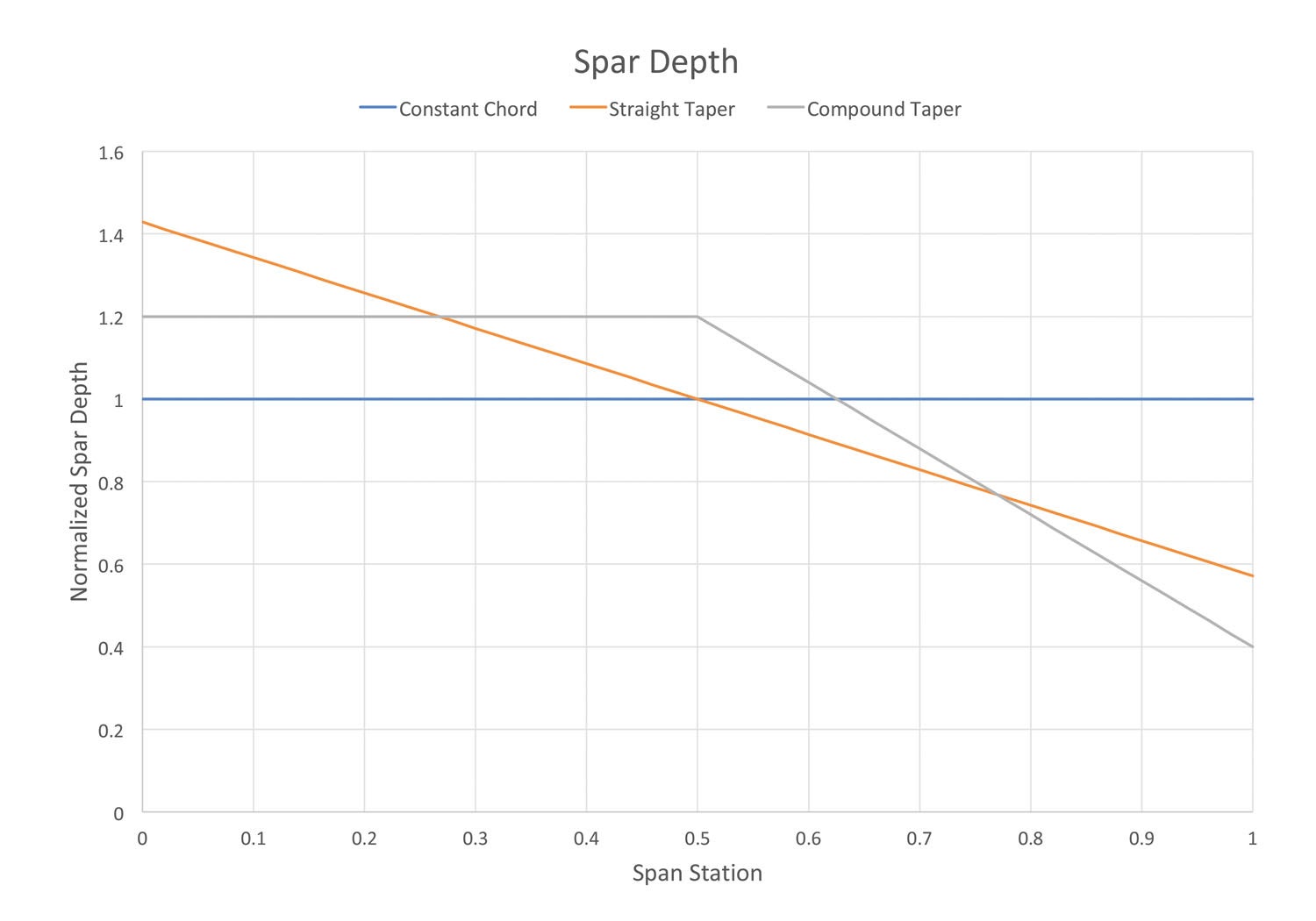
Figure 2 shows the relative depth of the spar as a function of span station for all three wings. It is normalized so the depth of the spar is shown as 1.0, and the depth of the spars of the other two wings are shown as the ratio of their spar depth to that of the constant-chord wing.
Note that at the root, where the highest bending moment is, the straight-taper wing has a spar that is just over 40% deeper than that of the constant-chord wing. The compound-taper wing’s spar is 20% deeper at the root than the constant-chord wing’s spar.
The constant-chord wing has the combination of highest bending moment and shallowest spar at the root. Accordingly, it will have the heaviest structure. To get an idea of how significant this is, look at Figures 3 and 4.
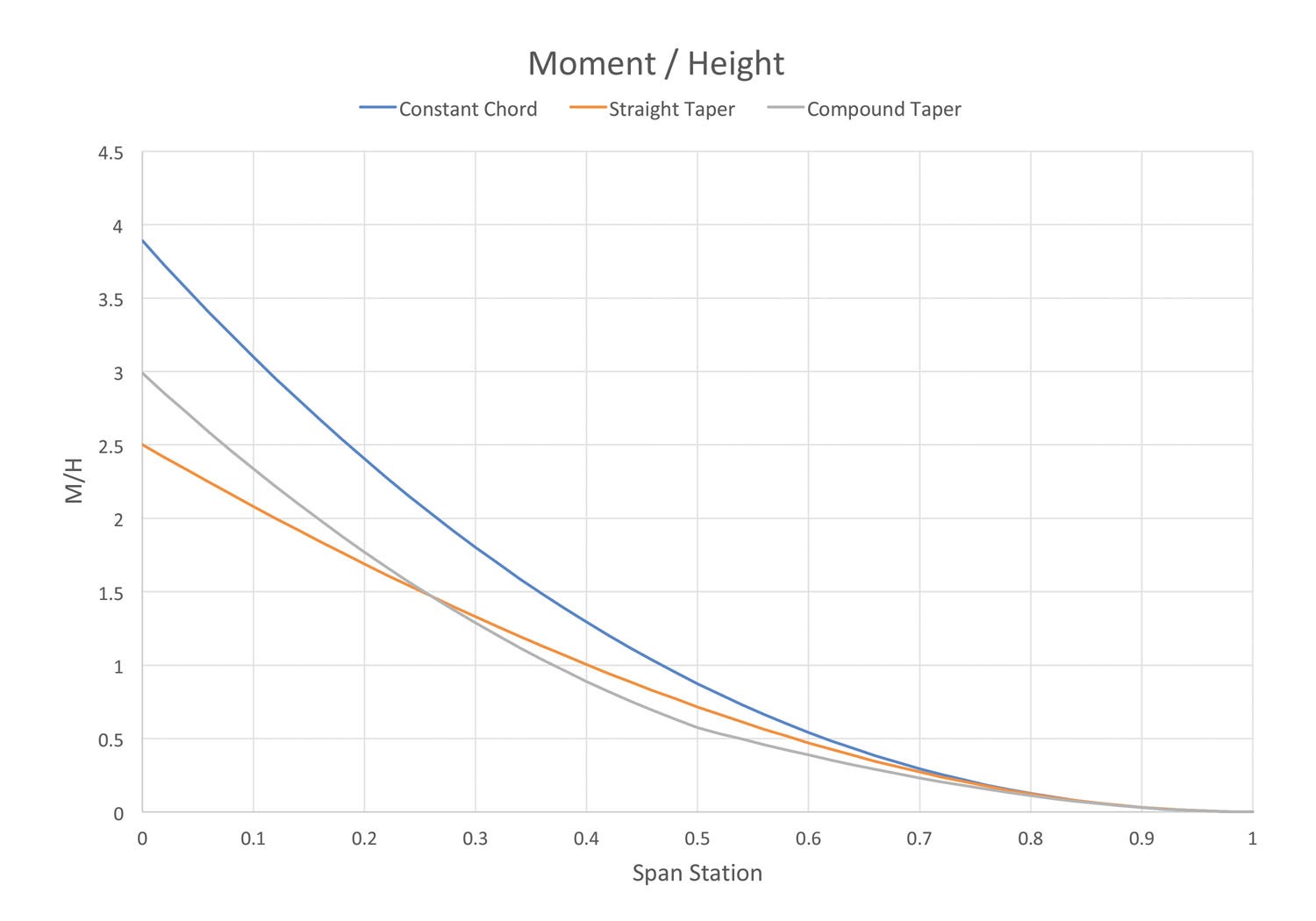
Figure 3 shows the ratio of moment to spar depth (M/H) as a function of span station. The lower this number is, the lower the loads on the spar caps will be. The constant-chord wing clearly has the highest spar cap loads over the majority of its span.
Notice that the straight-taper and compound-taper wings both have lower values of M/H over the majority of the span. The compound-taper wing will have higher spar-cap loads at the root than the straight-taper wing, but lower values outboard because of the different spanwise distribution of spar height. It will be slightly heavier than the straight-taper wing because the highest absolute moments are near the root, so the weight savings outboard will not be quite enough to overcome this.
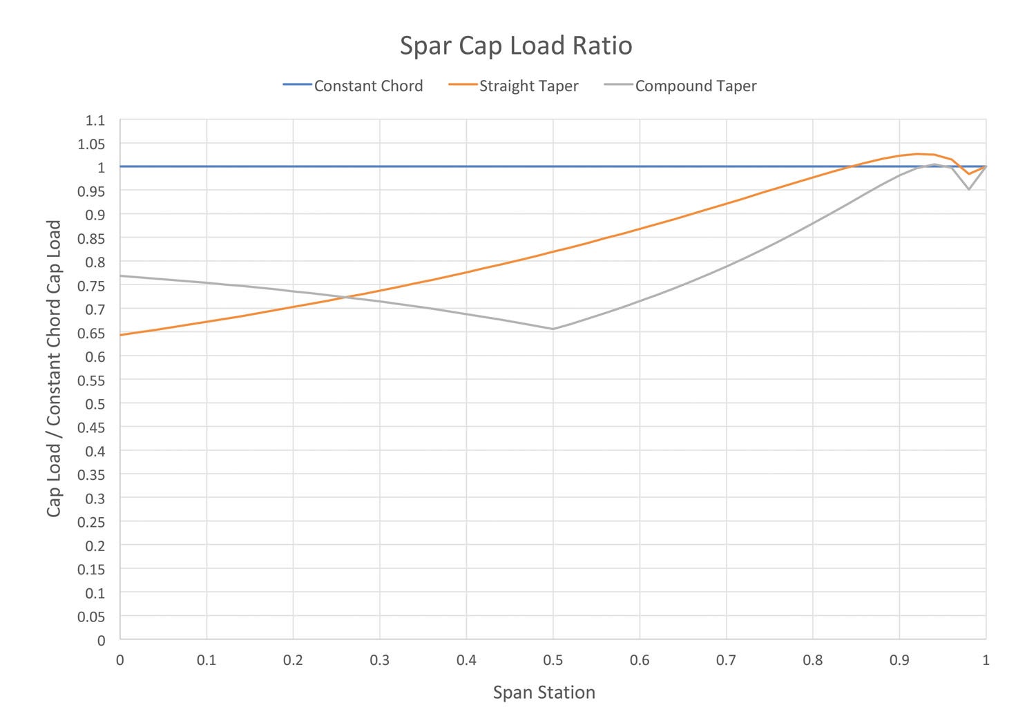
Figure 4 shows the spar cap loads for the three wings expressed as a ratio of the cap load divided by the cap load of the constant-chord wing at the same span station. Accordingly, the constant-chord wing has a value of 1.0 everywhere.
Looking at this figure we can see the overall effect of the combination of spar depth and span loading on the loads in the spar caps. The straight-taper wing’s spar caps at the root are only carrying about 65% of the load that the constant-chord wing’s spar caps must bear. For the compound-taper design the loads are slightly more than 75% of the value for the constant-chord wing.
Note also that except near the extreme tip where the loads are very small, both of the taper-wing designs have lower spar-cap loads, so the beneficial effect on structure weight carries over most of the span and is not confined to the wing root.
Summary
A straight-taper wing or compound-taper wing will be significantly lighter than a constant-chord wing of the same span and area designed to carry the same weight airplane. This is not the whole story, however.
The designer can trade the structural advantage of taper in several ways to further improve the performance of the airplane. These potential advantages must be weighed against several other factors: Tapering the wing introduces some potential aerodynamic issues, particularly with respect to stall characteristics, and constant-chord wings have significant cost and manufacturability advantages over tapered wings.
We will dig deeper into these design trade-offs next month.


I think the success of the many popular homebuild kits is that they mostly have rectangular wings, and building them is easier than building taper wings. One example is the Vans airplane; and all the Piper Cub clones too.
The compound taper with a semi-cranked wing would allow a simpler construction at the wing root where bad things can happen. See the less than ideal joint of a Piper Cherokee Arrow. The spar could go straight through, no bends, and simple shear connections. See the Jodel D140. The center section remains simple to build with some compromise to the outer section where loads are much lower.
Comments are closed.